HOME
HOME
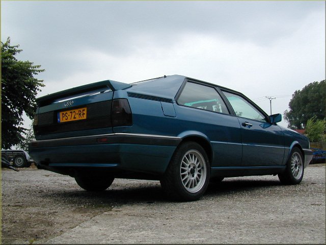
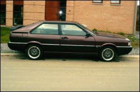
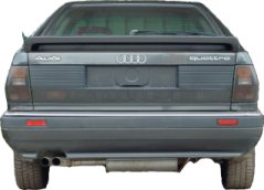
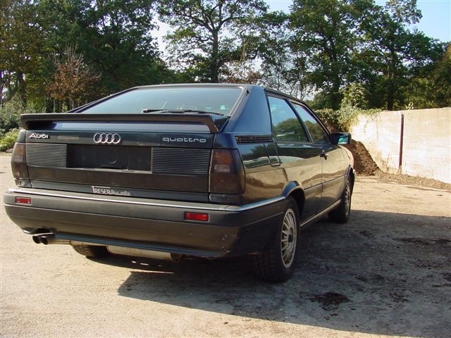
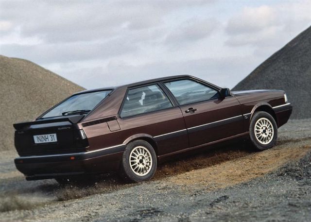
The Coupe quattro
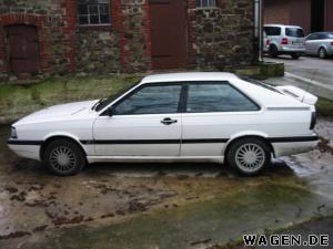
My CQ
Ongoing Restoration
Gallery
Info / Data
Suppliers
Links
T85q.com
Audi Coupe quattro Digital Dash conversion
According to the TFA (The Family Album....), the Coupe Quattro was optionally fitted with the green WR UR quattro digital dash. This however, seems to have mainly been restricted to Left Hand Drive cars... But there are rumours that several RHD examples got the dash as well.... It's also shown in the handbook for the RHD cars, with a full english translation for it's operation, etc.On that basis, I've decided to install the Digital Dash on my CQ. I was unable to aquire the green WR dash (too bleeding expensive!), so I managed to get an Orange dash from a Coupe GT. These dashes was fitted to the North American '86 and '87 Coupe GT's.
There is the added bonus in using this dash in that documentation on the pin-out and the signals for the dash being readily available on the web.
Dash Documentation
Audi published a booklet "Electronic Instrument Display for the Audi Coupe GT". This details the pin-out of the 35 pin connector at the rear of the dash, and what each pin is connected to, and what each pin does. You can find a zipped copy of the booklet here : GTDigiDash.zipI've also listed links to the individual pages as well.
Front Cover Table of Contents
Page 1 Page 2
Page 3 Page 4
Page 5 Page 6
Page 7 Page 8
Page 9 Page 10
Page 11 Page 12
Page 13 Page 14
Page 15 Page 16
Page 17 Page 18
Page 19 Page 20
Page 21 Page 22
Page 23
Parts List
A bit of research established a shopping list of parts that are required to do this...I've listed the necessary parts below.
1. Digital Dash unit (suprise suprise)
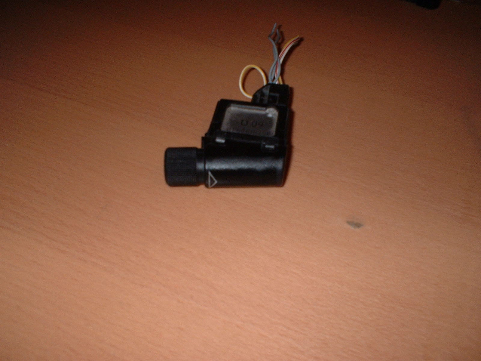
2. Gearbox speed Sensor
3. Fuel metering plate for the KV engine with potentiomer
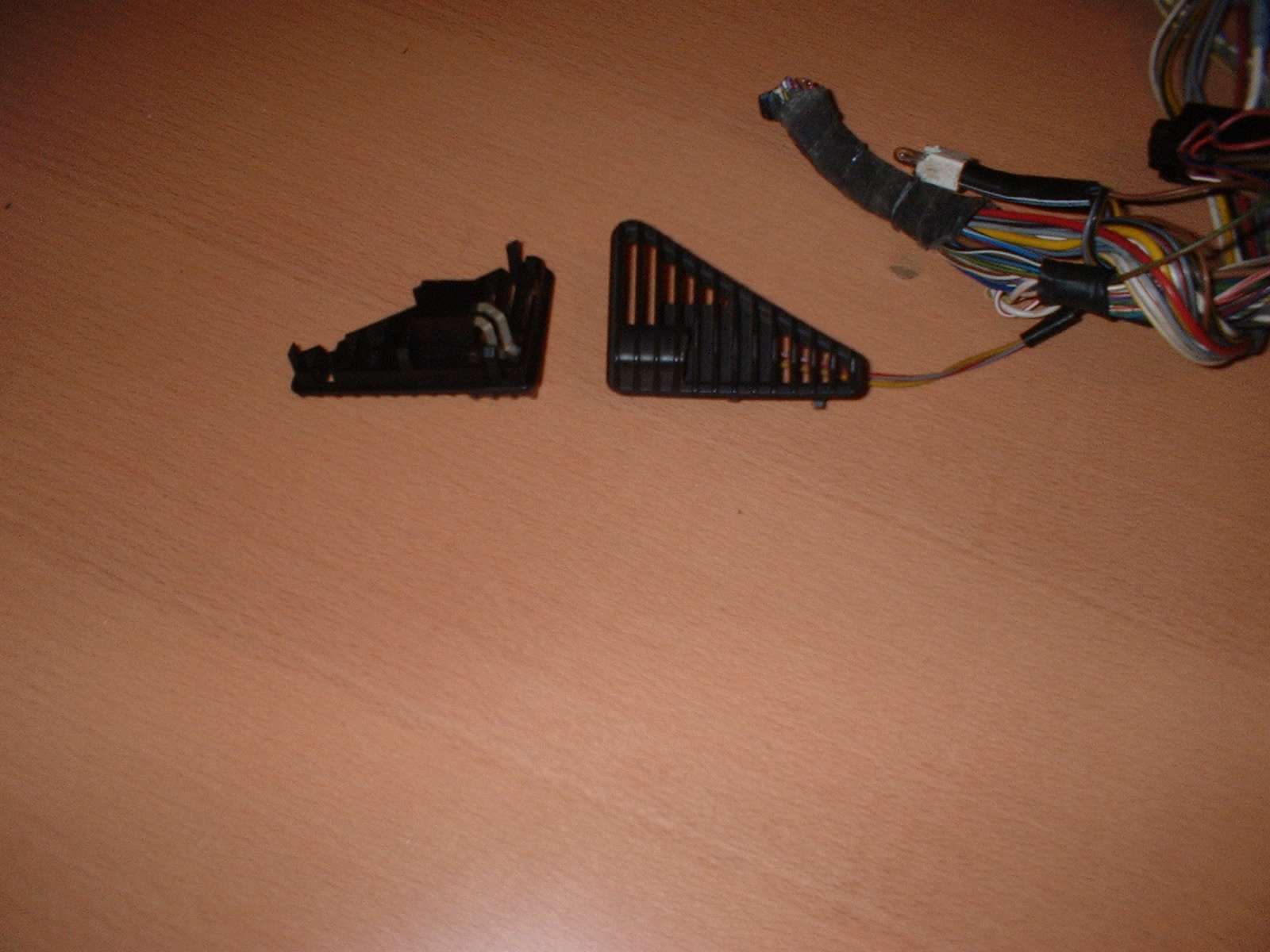
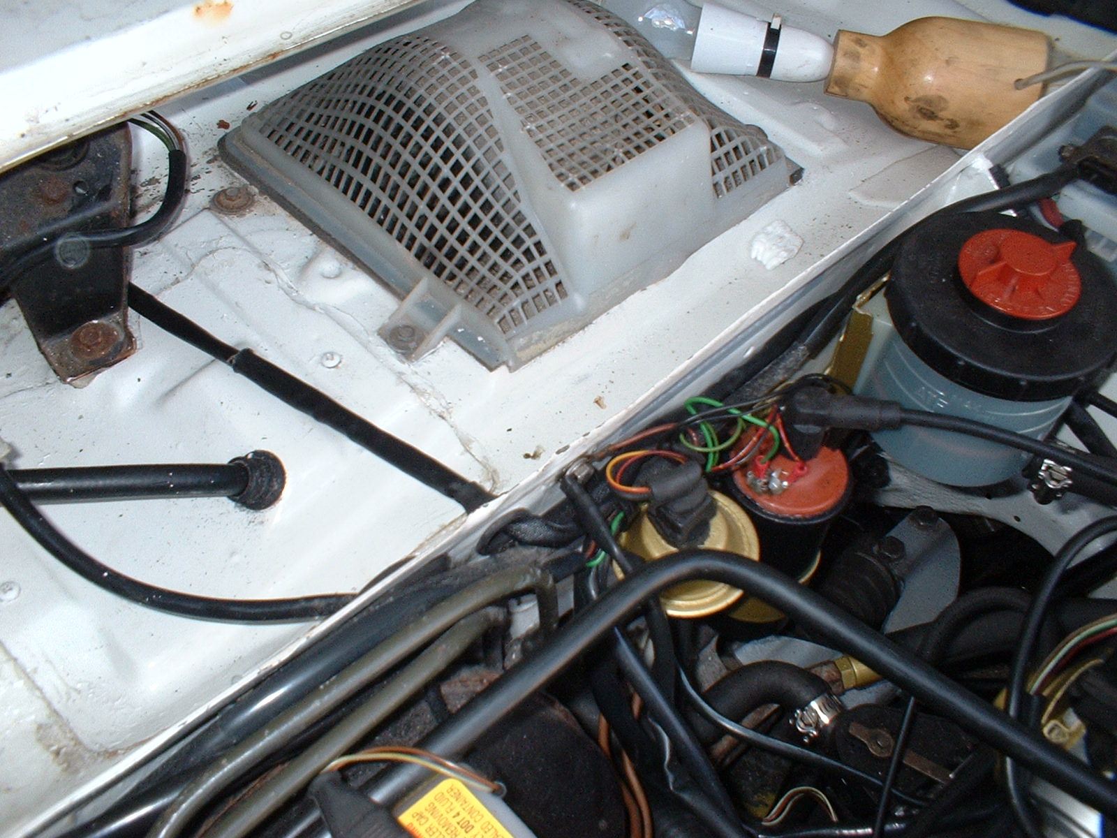
4. Light sensor (in the small triangular dash vent)
5. Dash backlight adjuster, digital dash version
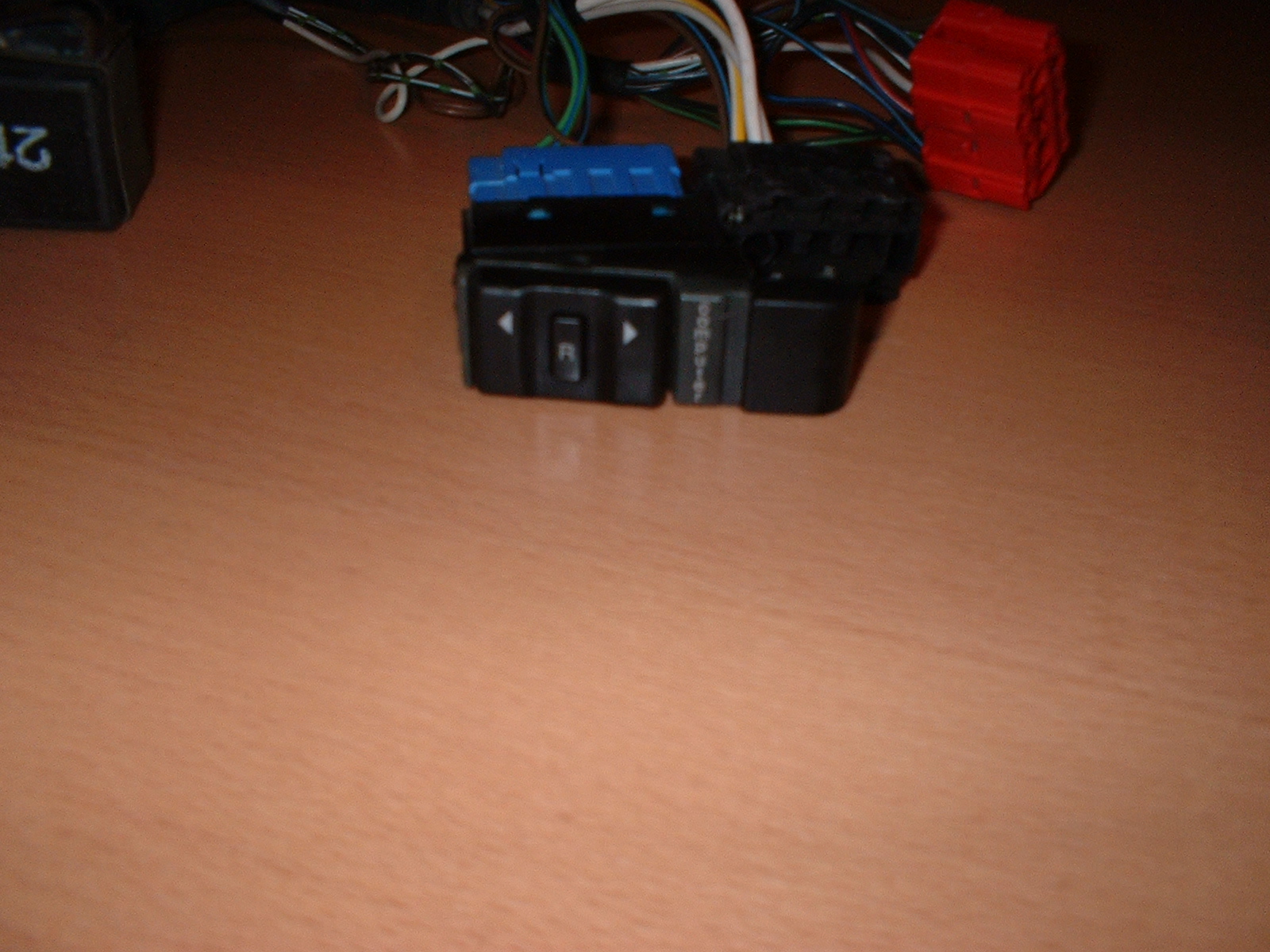
6. Computer switch
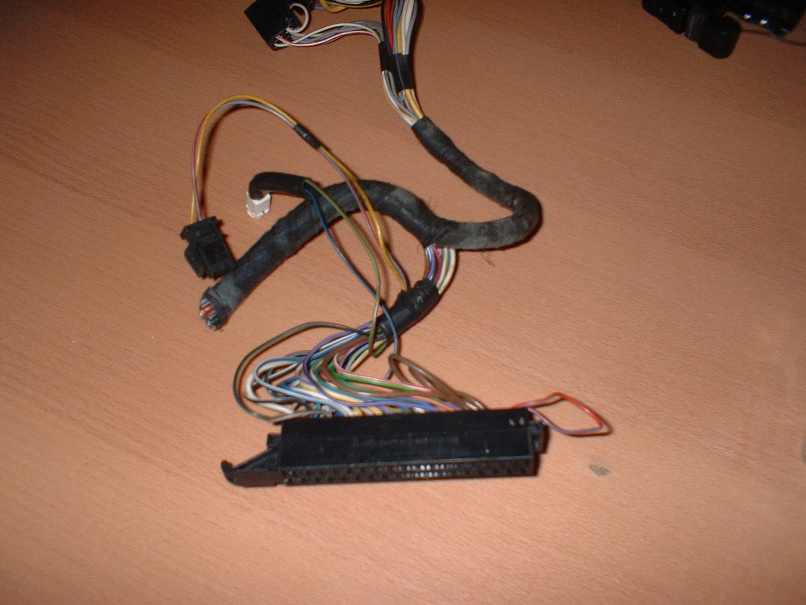
7. Multi-plug conector for the back of the dash unit, with wiring tails.
8. Sundry items such as wire, conduit, connectors etc.
I managed to source everything from the USA, except for the metering plate which came from Germany.
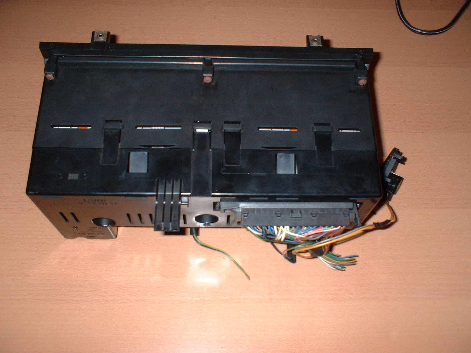
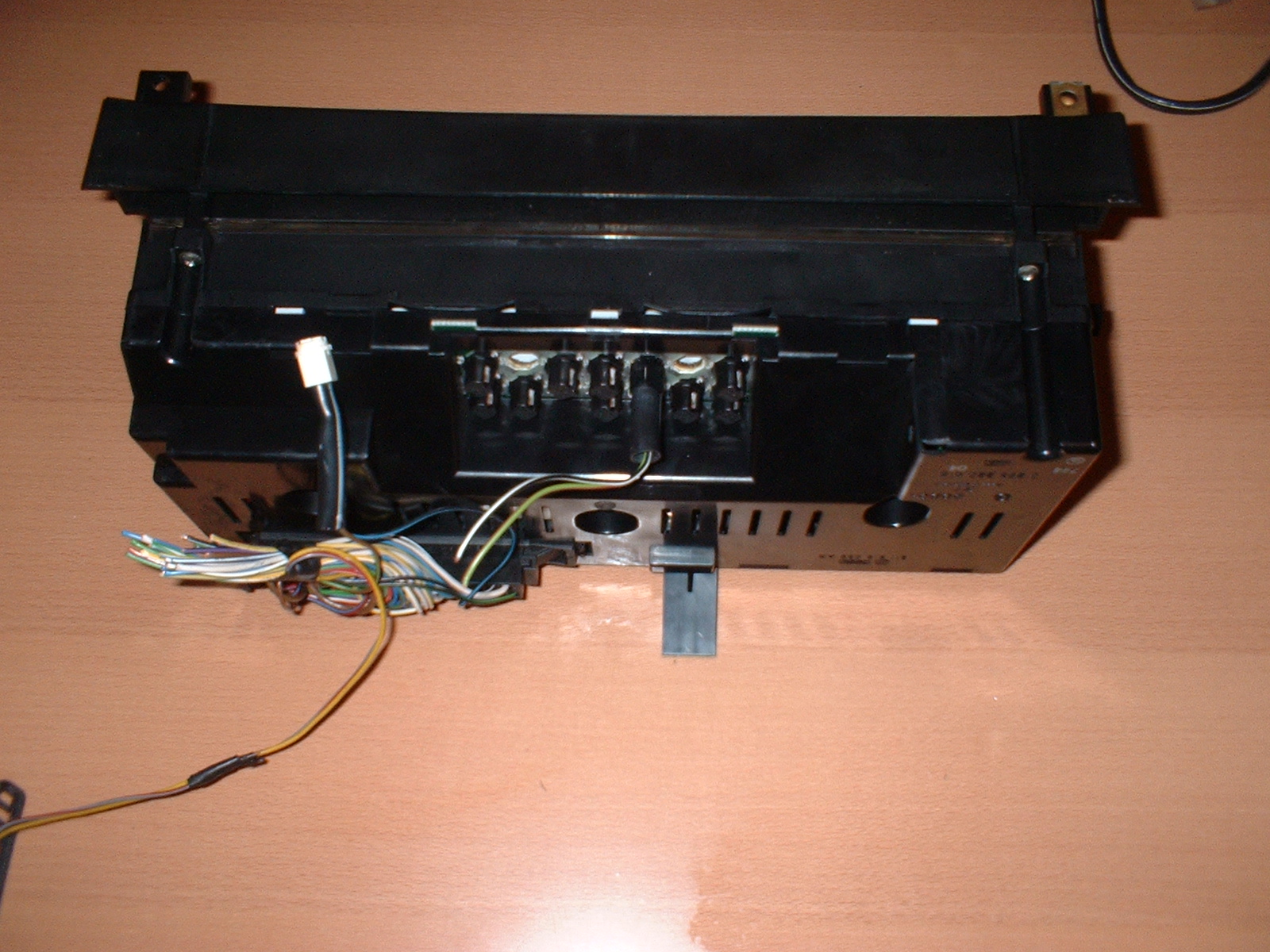
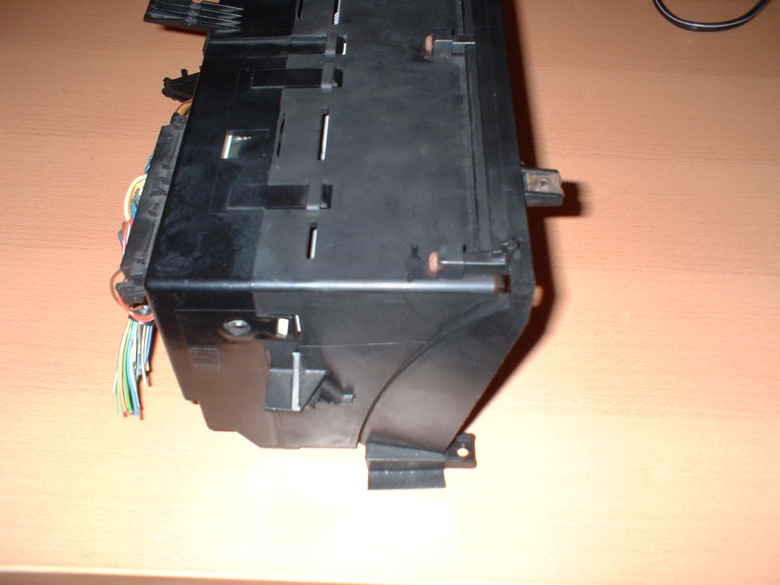
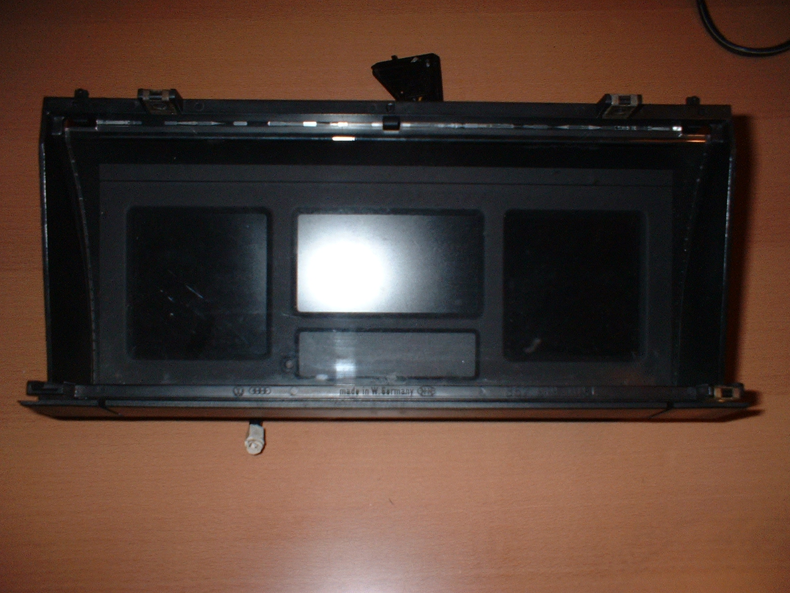
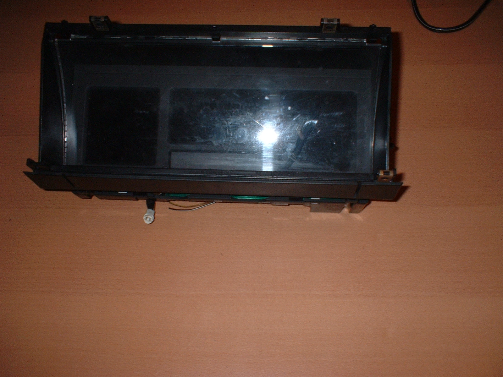
Digital Dash Unit
Here are some photographs of the unit whilst out of the car
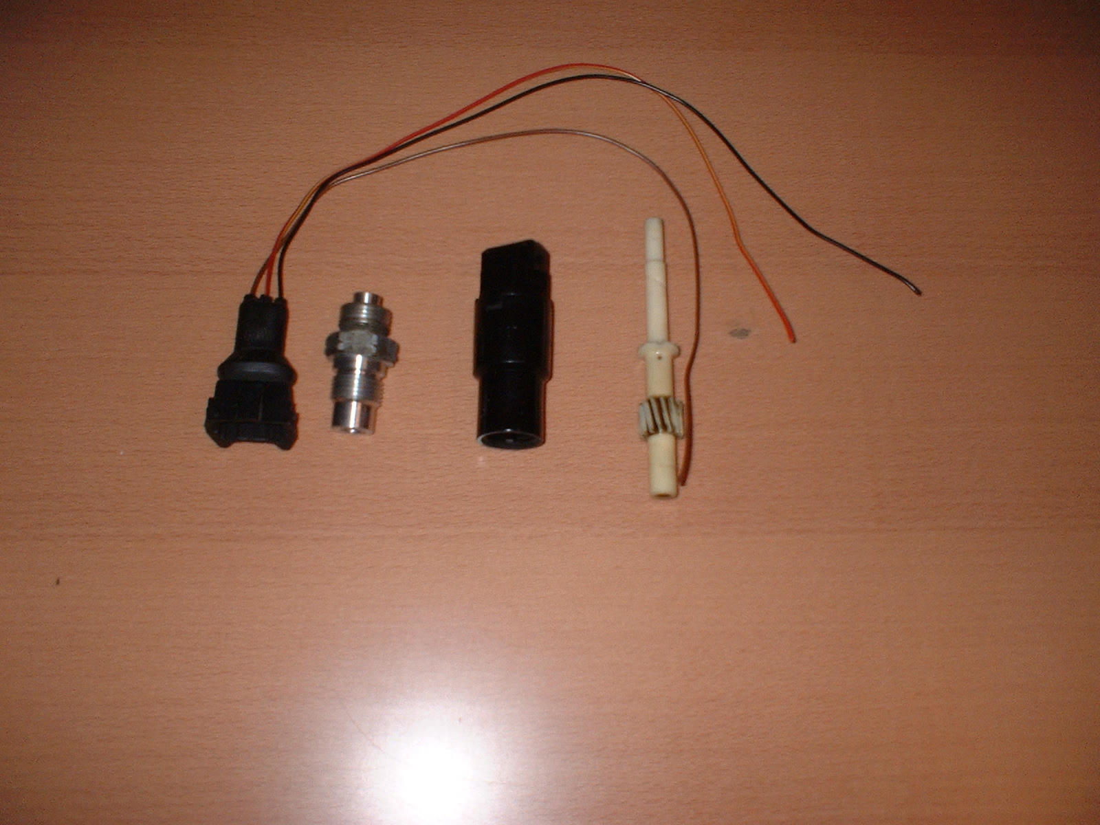
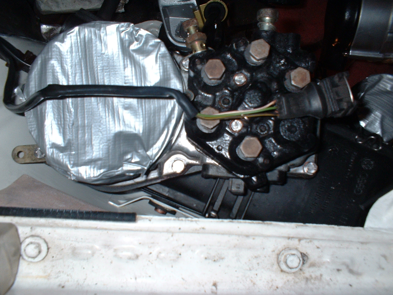
Gearbox Speed sensor
The speed sensor is the black cylindrical item. You also need the three pin conector (shown with tails attached). panerai replica sale The aluminium item is the threaded boss from the gearbox, and the ivory coloured item the speedometer cable drive gear. The speed sensor just screws onto gearbox where the speedometer cable normally goes.
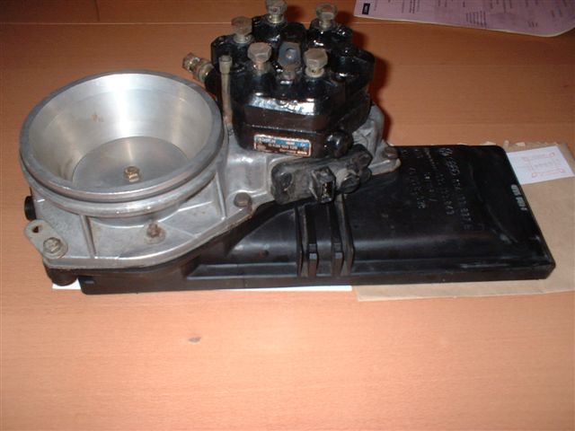
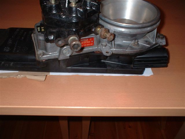
Fuel Metering plate
On the side of the metering plate is a potentiometer. This measures the angle of the "flap" that meters the amount of fuel being delivered to the engine. The dash uses this information for calculation of MPG, etc. You can see the potentiometer on the side of the metering plate.
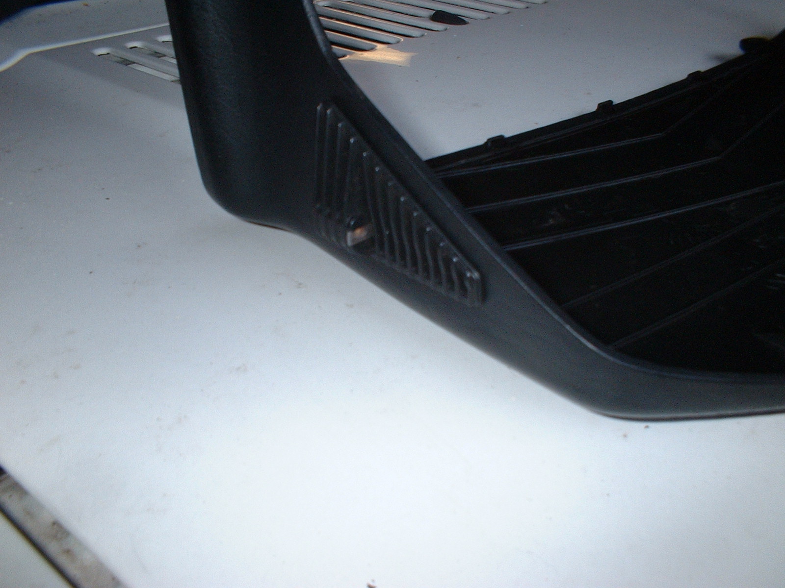
Light sensor
This tucks into the triangular vent in the side of the dash top cover. breitling replica sale The dash uses this sensor, and another light sensor on the face of the main dash to set the brightness level of the dash.
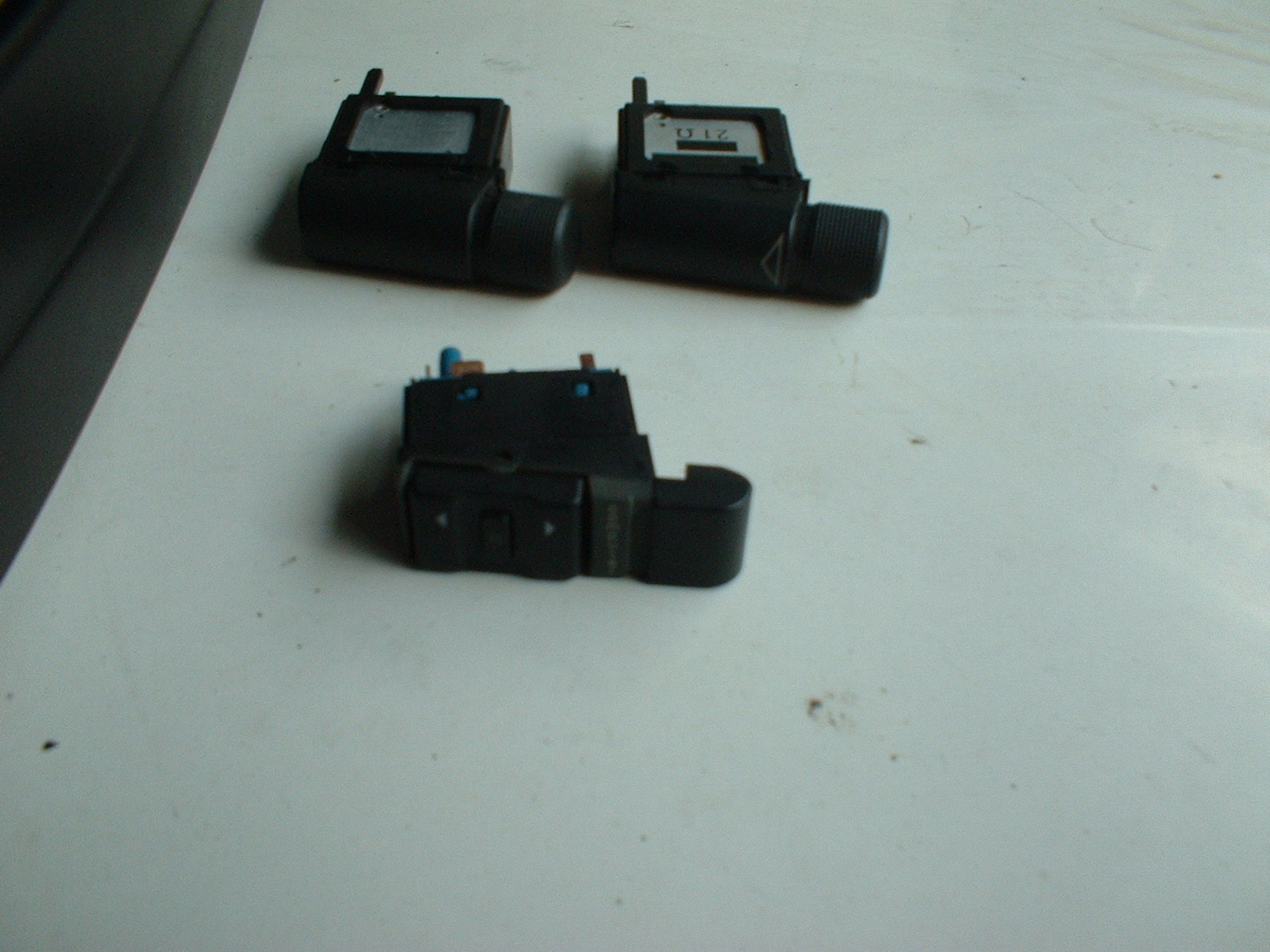
Dash backlight adjuster
Used to adjust the light setting of the dash, plus it works in conjunction with the computer switch.
Computer Switch
Used to control the dash, change from kph to mph, etc. etc.
Multi-plug connector
This connects the dash to the rest of the car
Project Starts!
07 Jan 2006
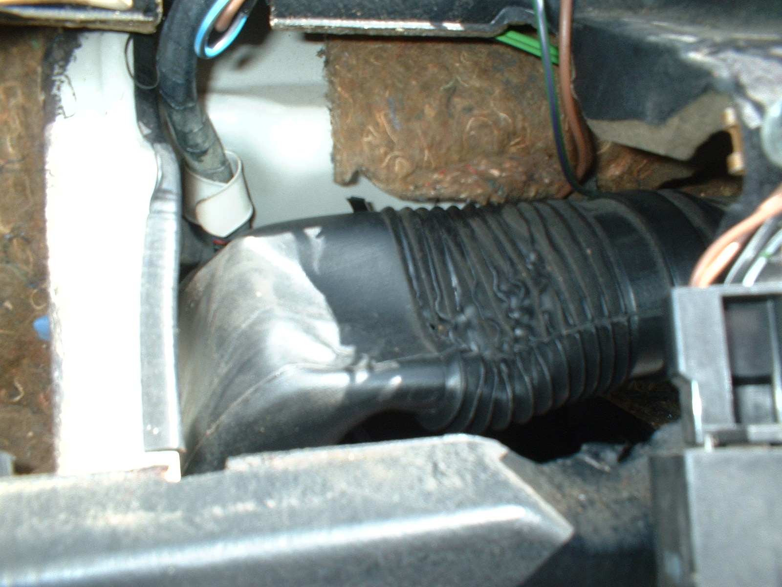
The Air Filter box is now installed in the car. The standard CQ loom also includes the connector for the metering plate potentiometer. panerai replica sale The other end is a 4 pin red connector behind the dash somewhere. It's as simple as just plugging it in. I hope....
15 Jan 2006
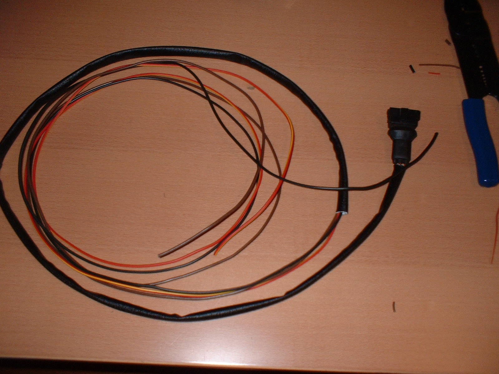
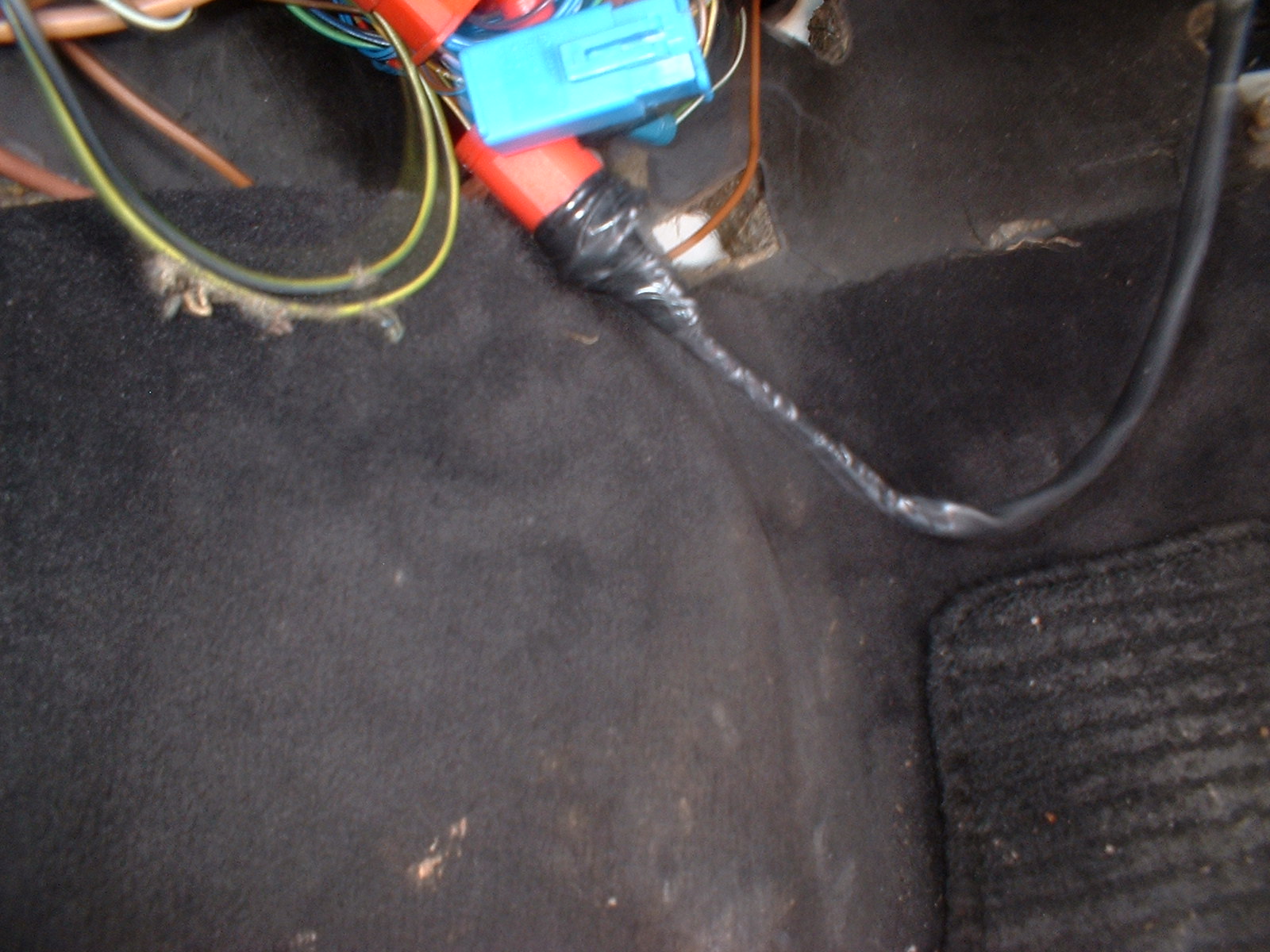
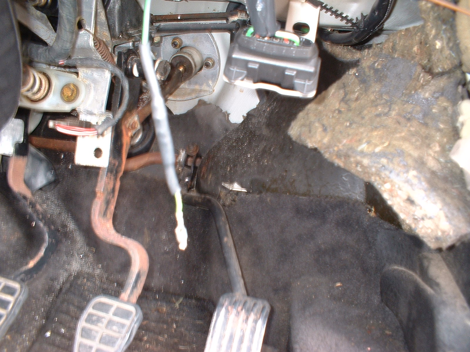
I got some of the correct colour wire for the speed sensor connections. Spliced it in, and covered it with wear resistant sleeving. Once the speed sensor is fitted, the sleeved cables will follow the speedo cable route through to behind the dash.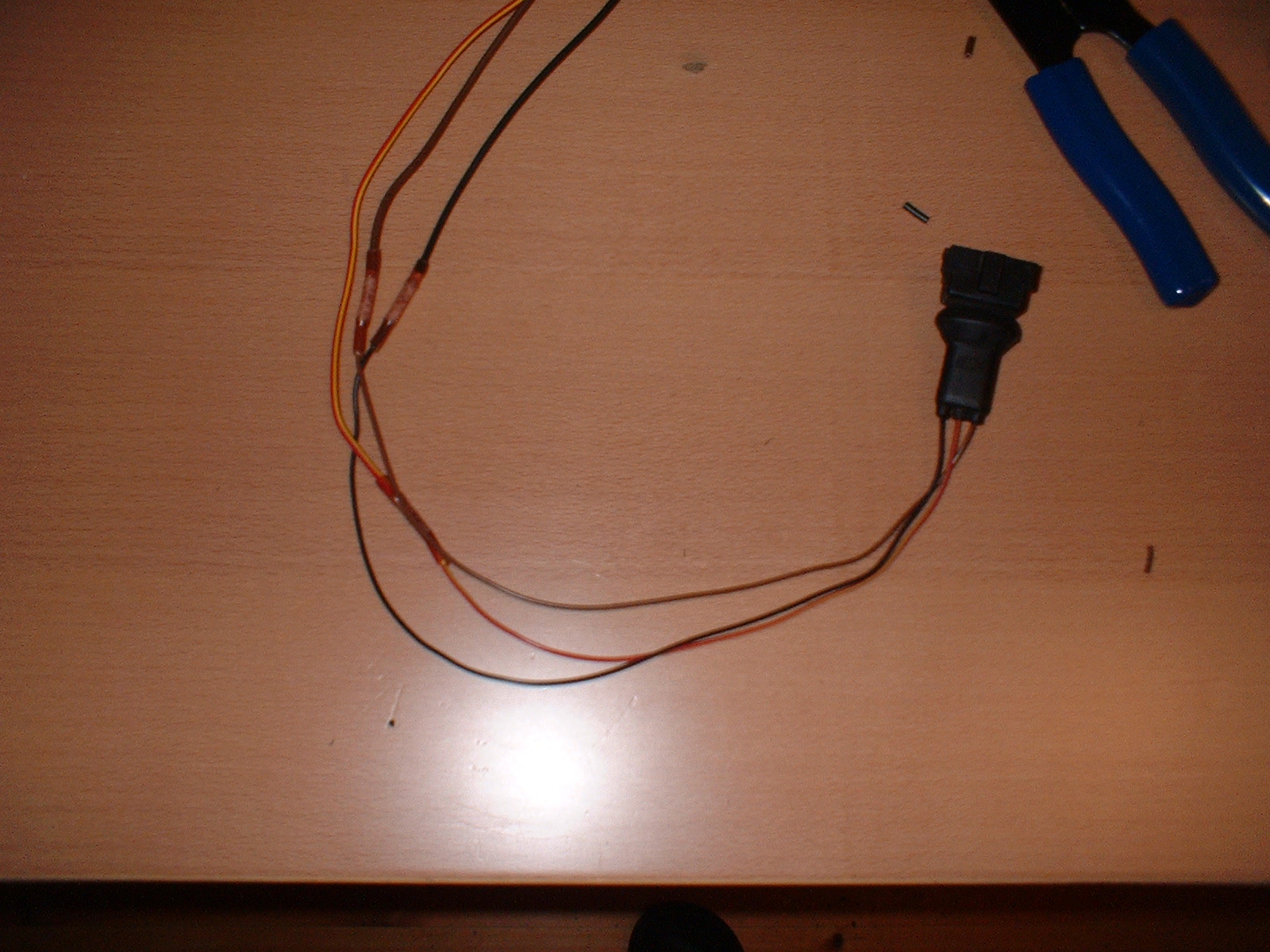
13 May 2006
The speedo cable was removed from the gearbox end by just undoing it. At the speedo end, it's a bayonet style connection which is quite hard to get at, but not impossible. The Speedo cable fits through 2 grommets, one behind the wiper motor, and one in the firewall, near to the coil. omega replica sale I kept the speedo cable for possible future refitment. I also had an old damaged cable from which I removed the two grommets. replica watches sale The speed sensor just screws on onto the gearbox, and the harness plugs in. rolex replica uk I routed the cables up behind the PAS resevoir, through the firewall, and in behind the dash. Some liquid soap allowed me to easily fit the grommets.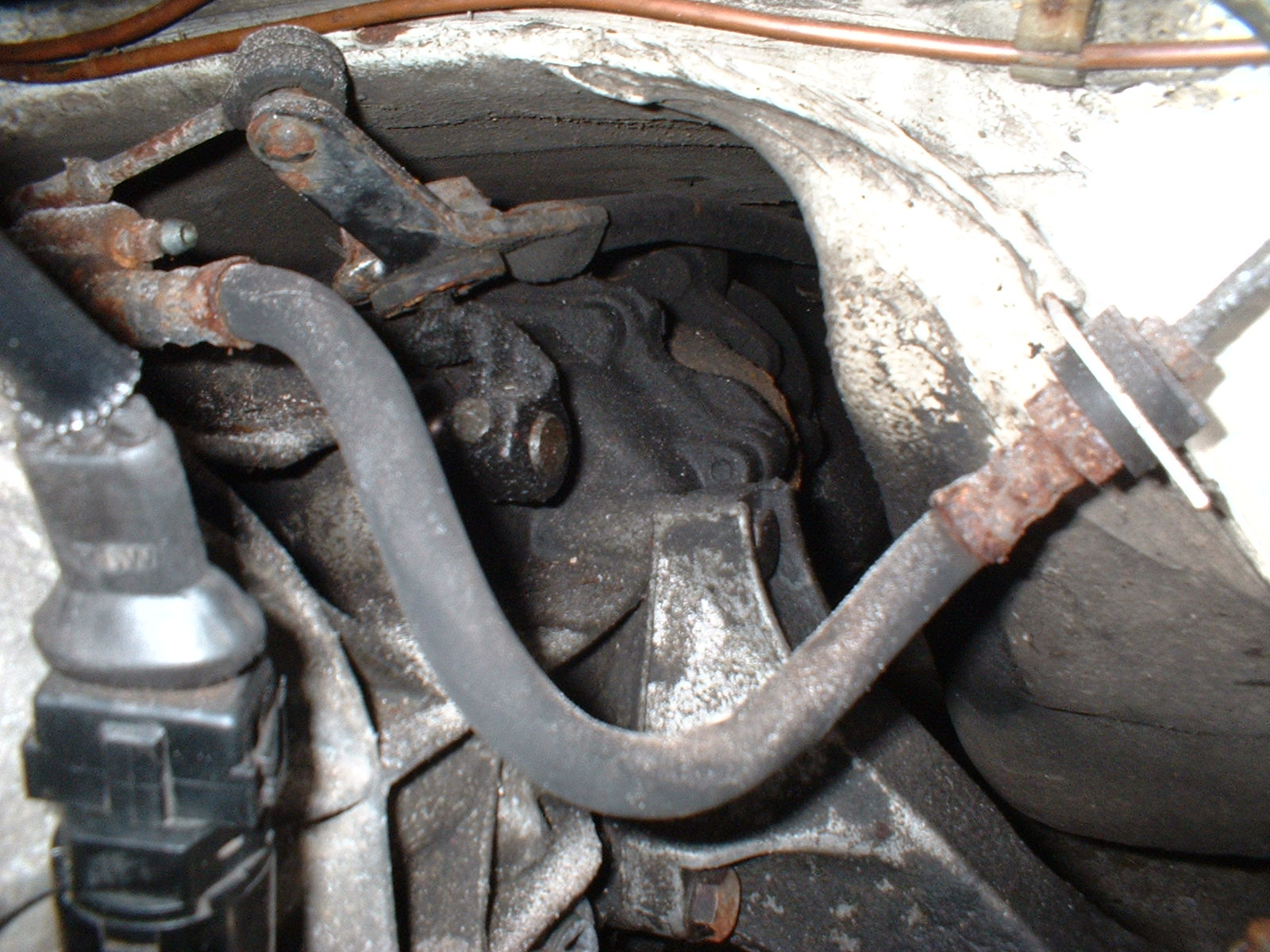
Now "all" that remains is to make up the behind the dash wiring loom, and fit the dash.....
18-22 May 2006
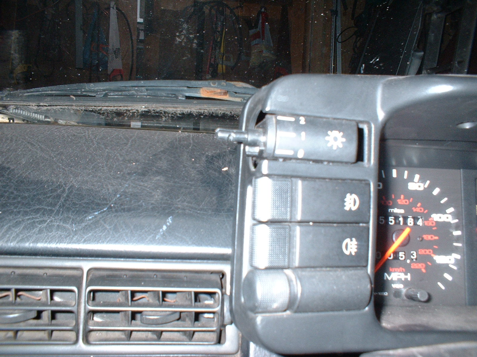
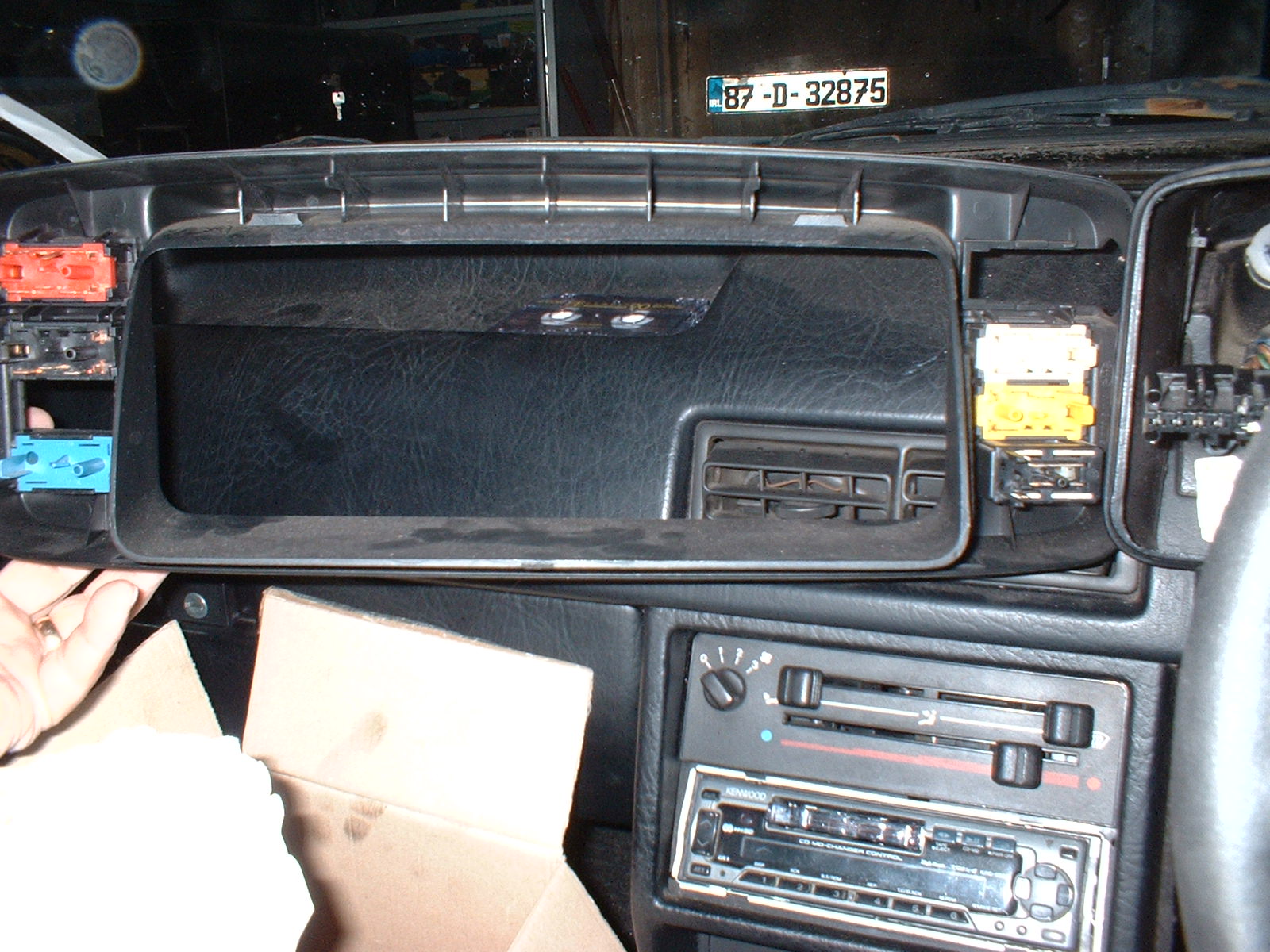
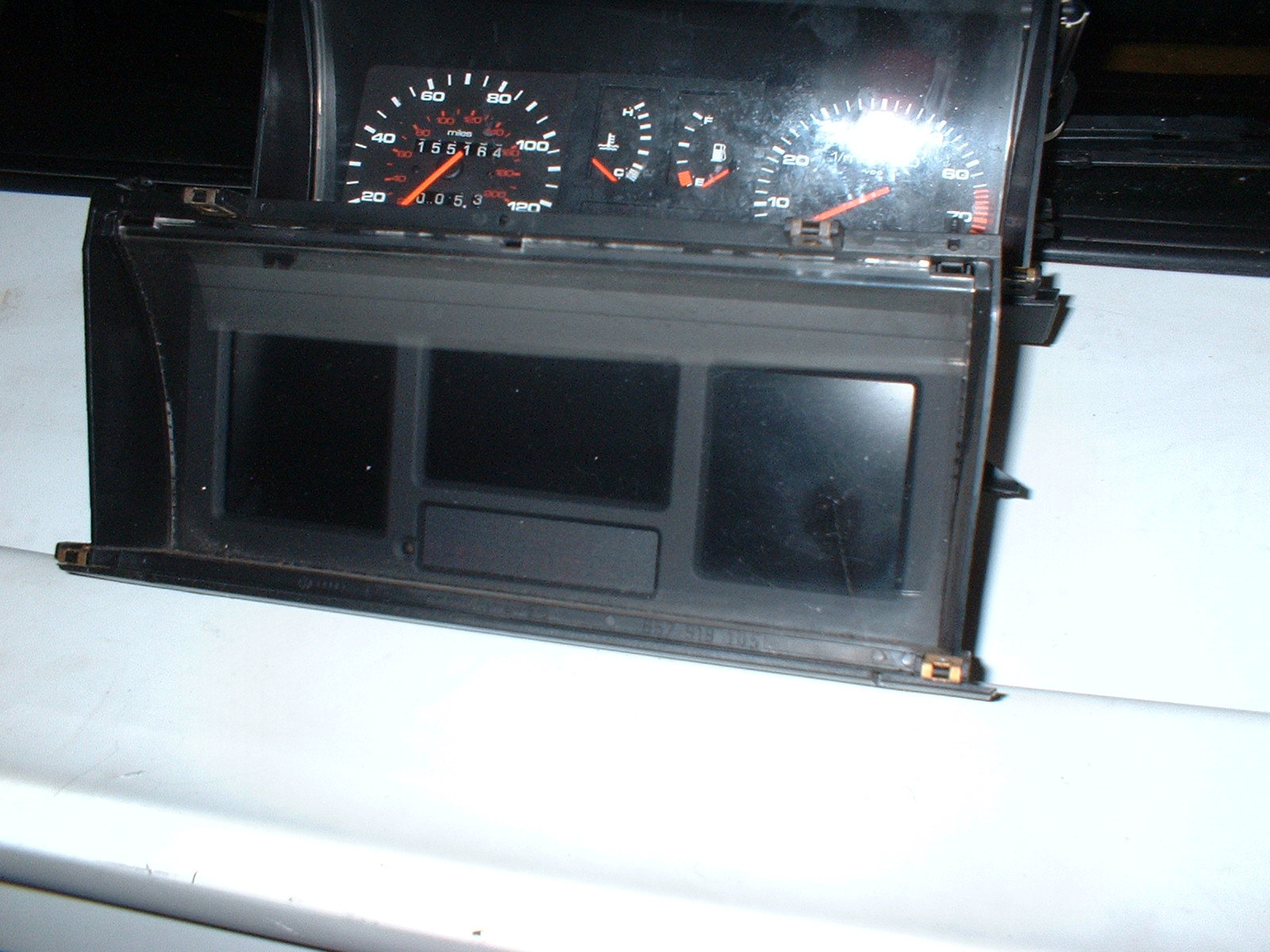
Here's the old dash still in situ
Remember to pull off the end of the lighting switch
The Fascia panel is held on by 4 self tapping screws. Remove these
and retain for later refit. Once the panel screws are removed, pull
the fascia panel towards you, and disconnect the wiring loom plugs
from the rear of the various switches. These are quite stiff, so be
carefull
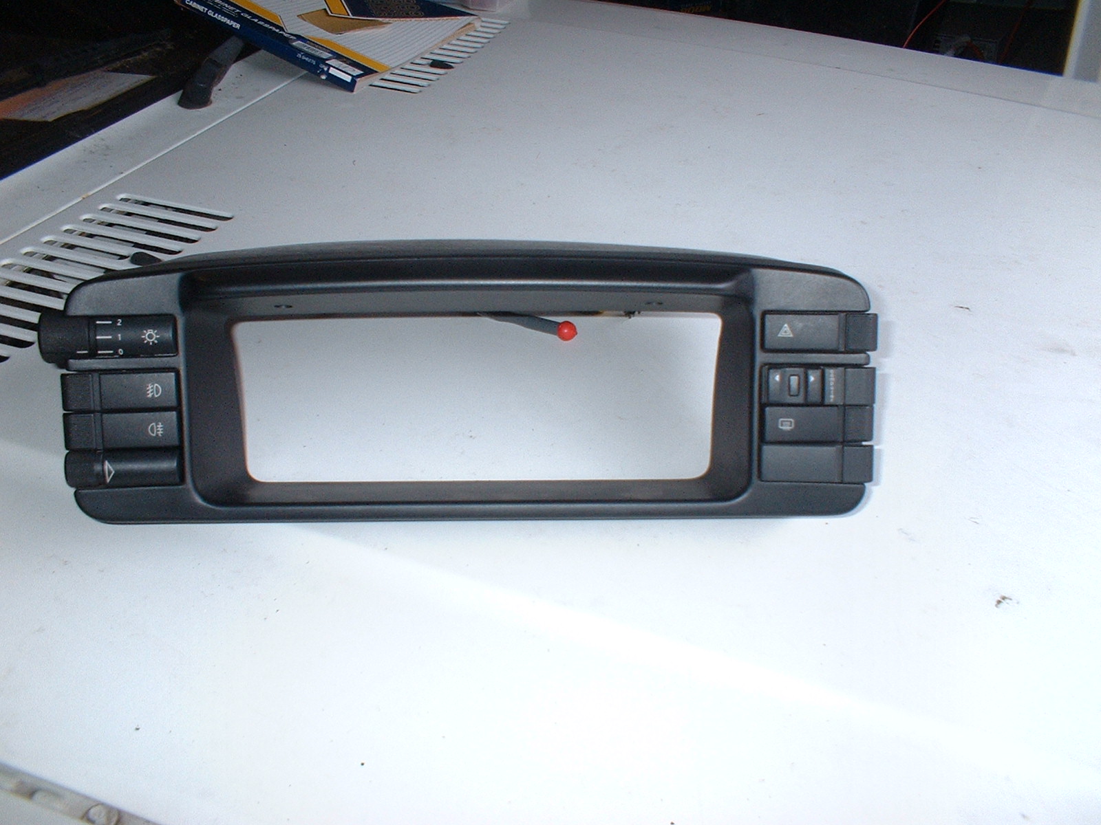
Rear of the fascia Panel, and the back of the switches. Note that
the switches and wiring loom conections are colour coded for
"easy" re-assembly
The instrument unit is secured to the main dash using 2 screws, one
at each side
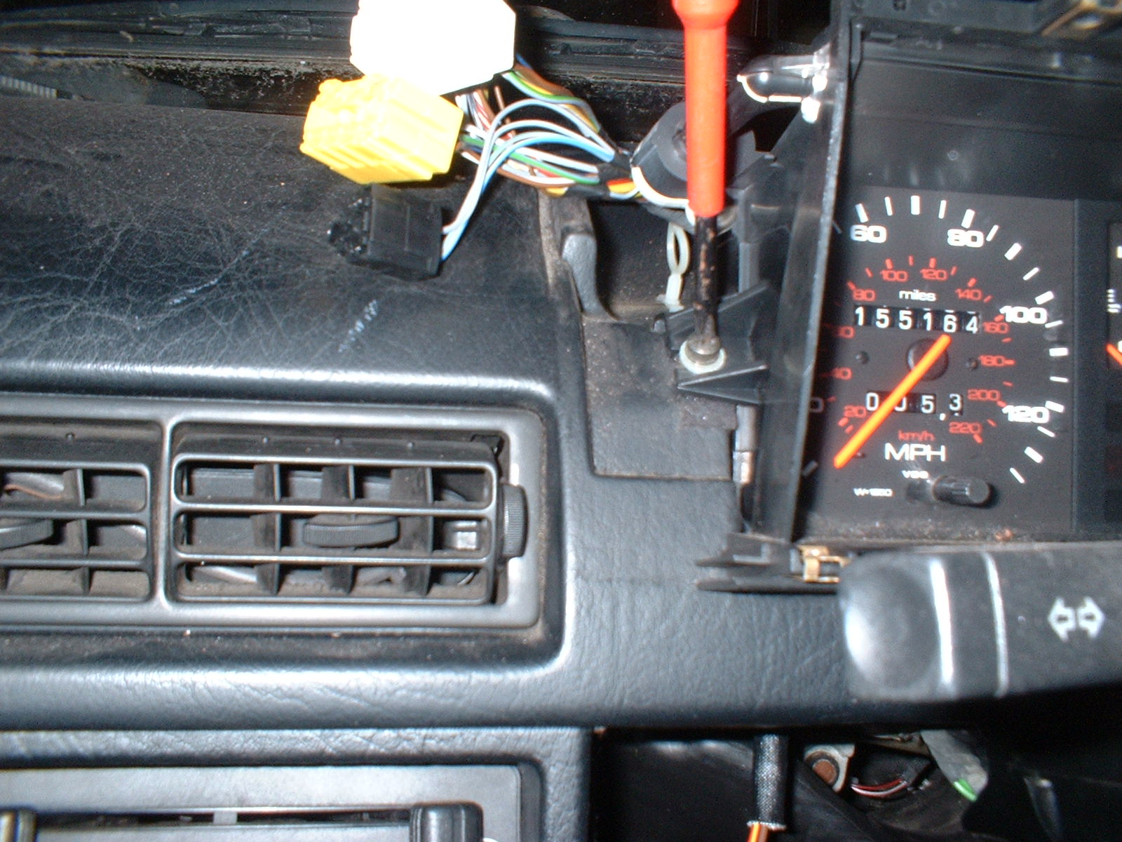
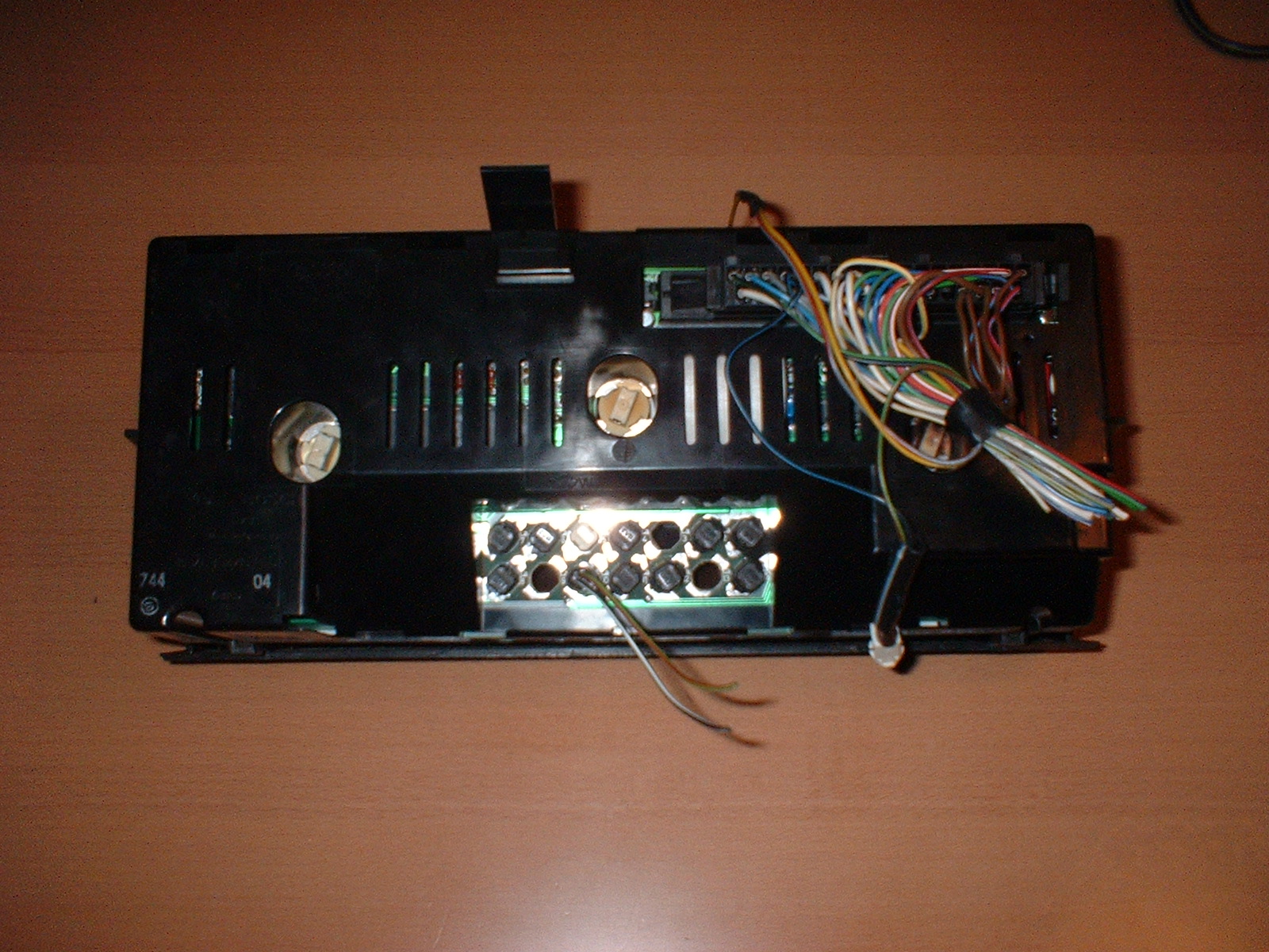
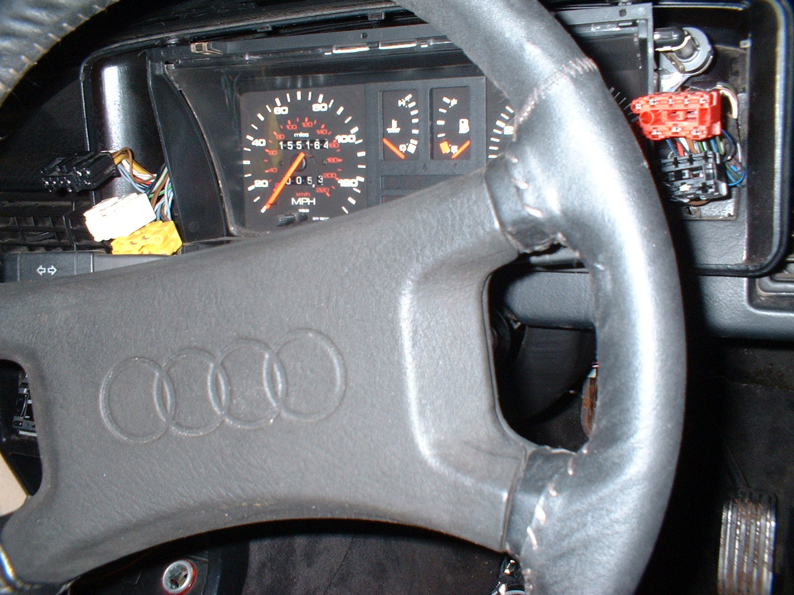
Here's the rear of the instrument unit, showing the White and Black
connectors.
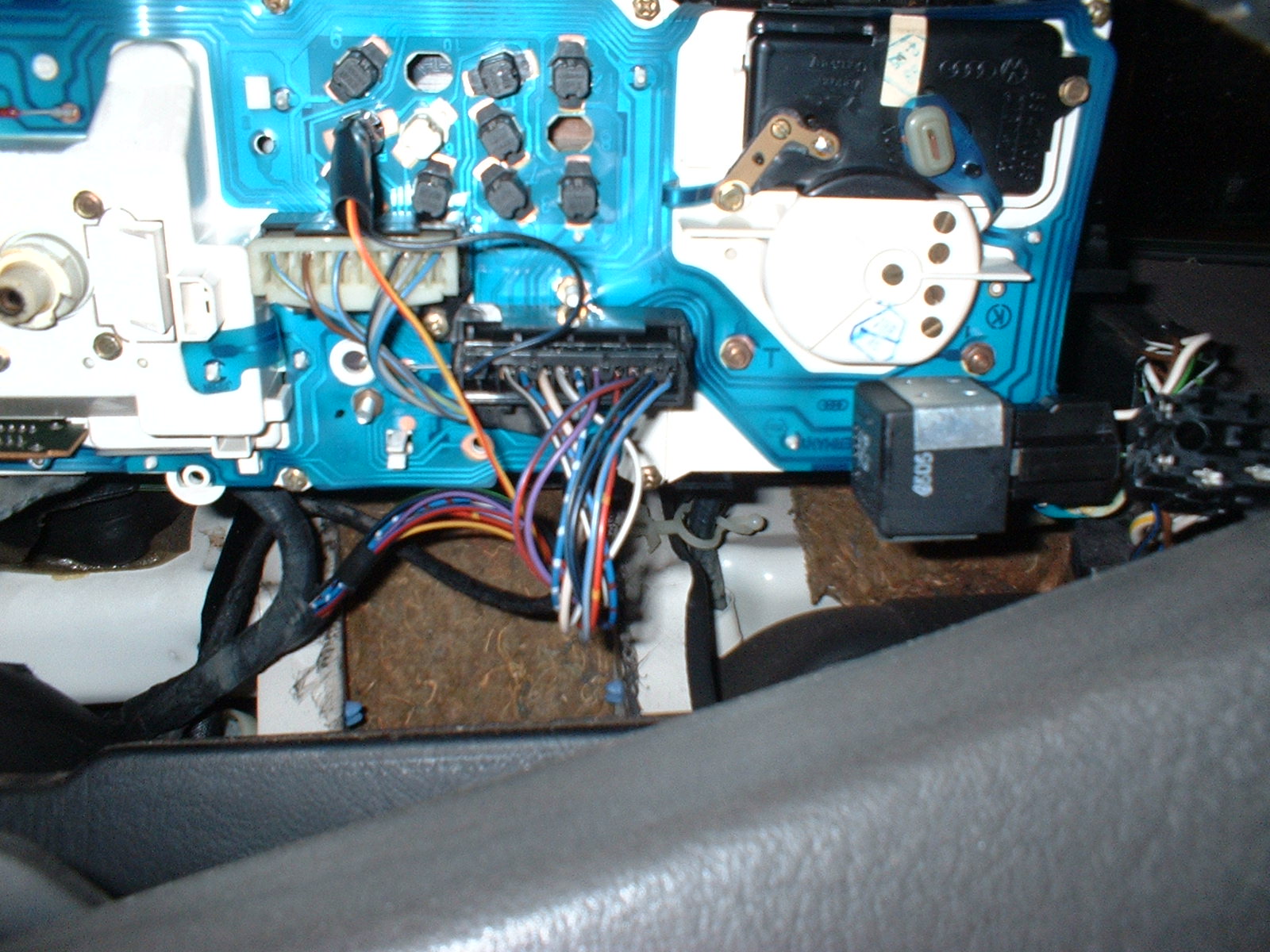
A bit blury, but this shows the blade connector on the back of the
instrument unit
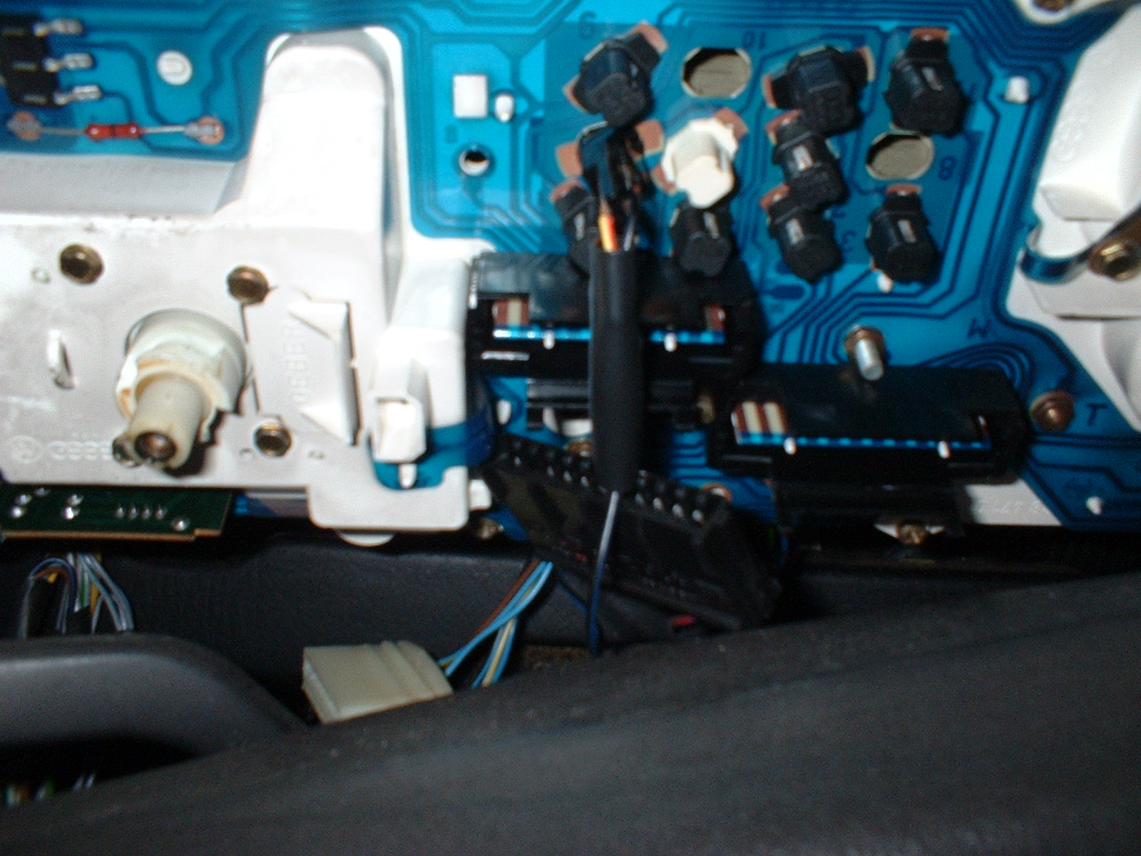
Instrument unit released and removed.
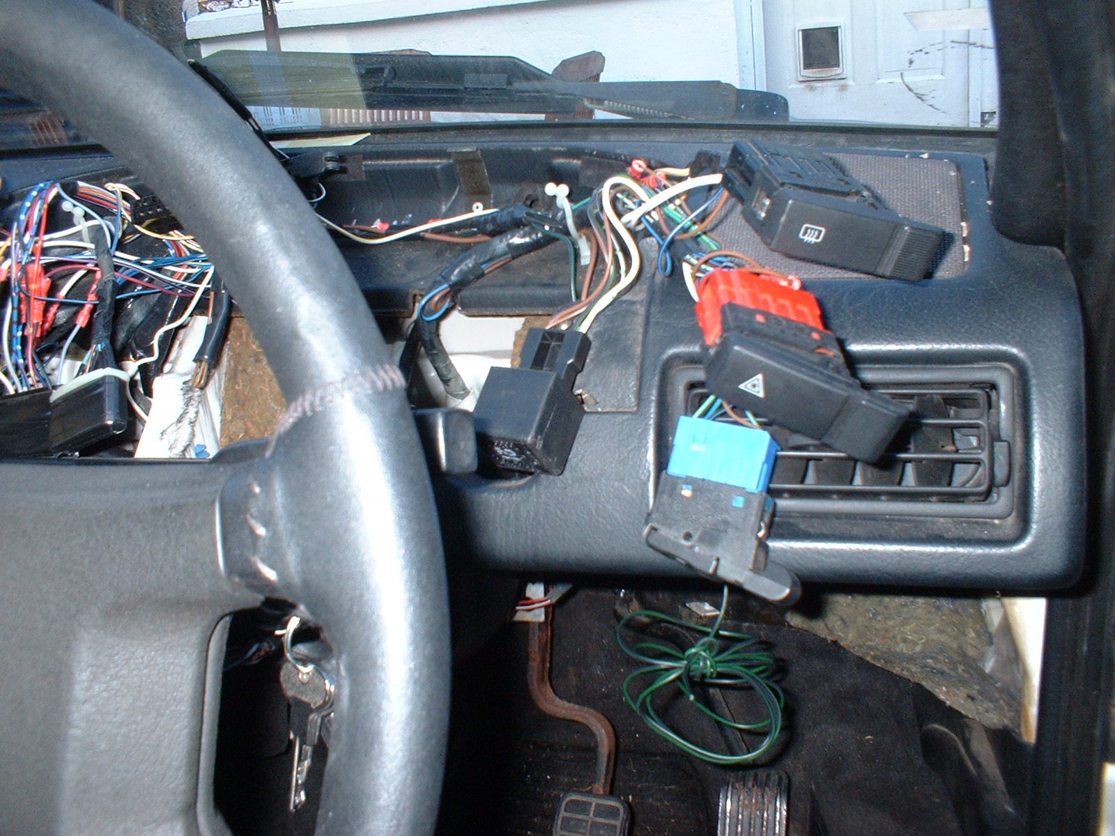
Out with the old, and in with the new.....
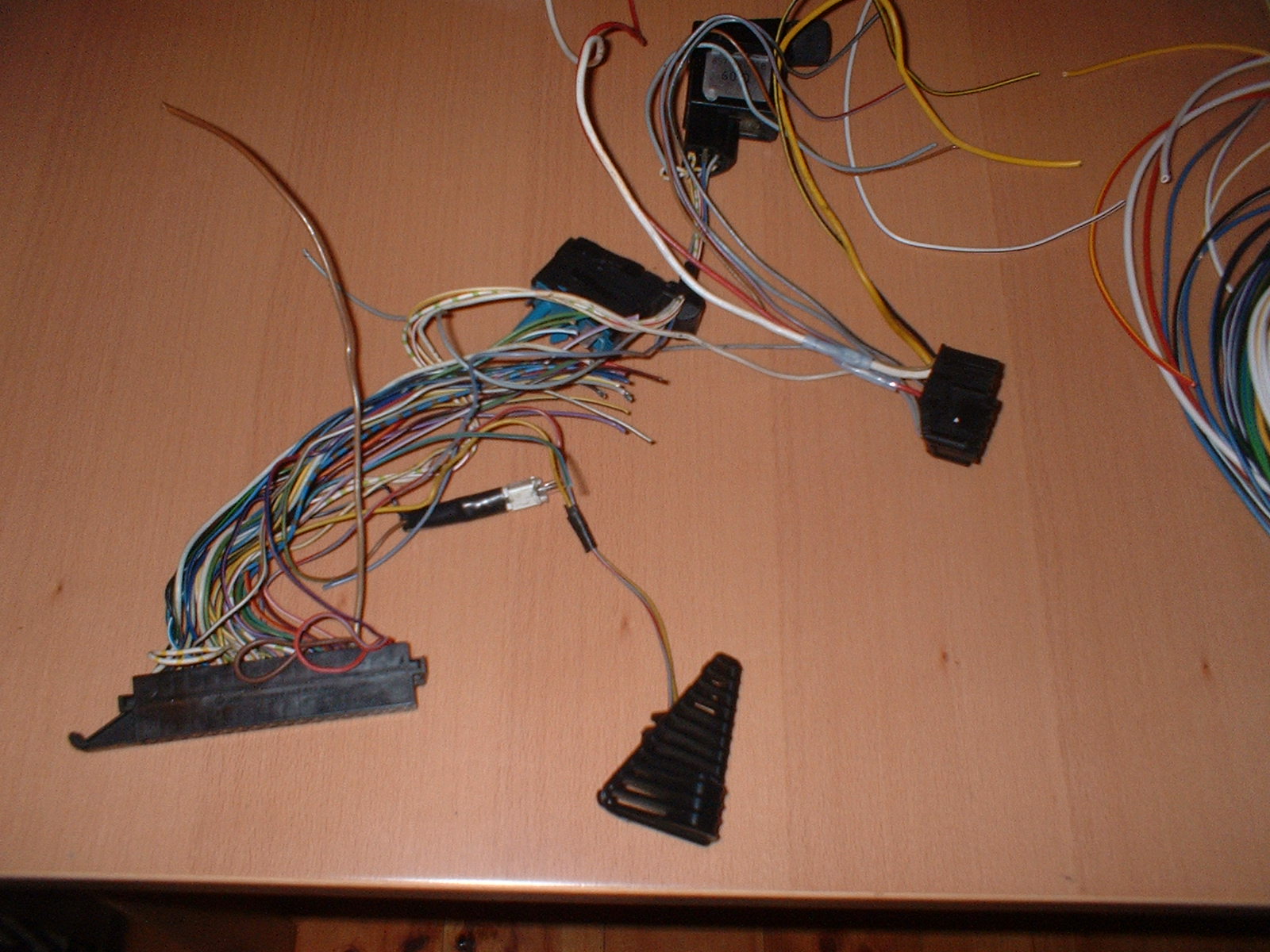
These is the wiring tail that came with the dash. The light sensor,
dimmer switch, and computer switch were all still connected
(handy....)
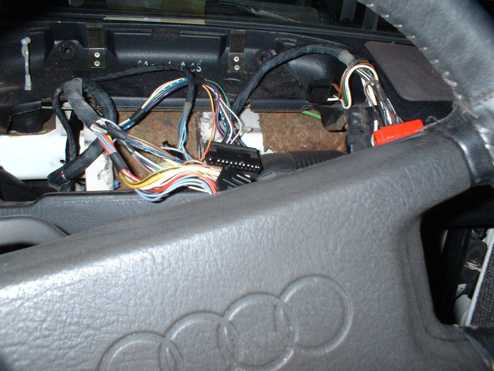
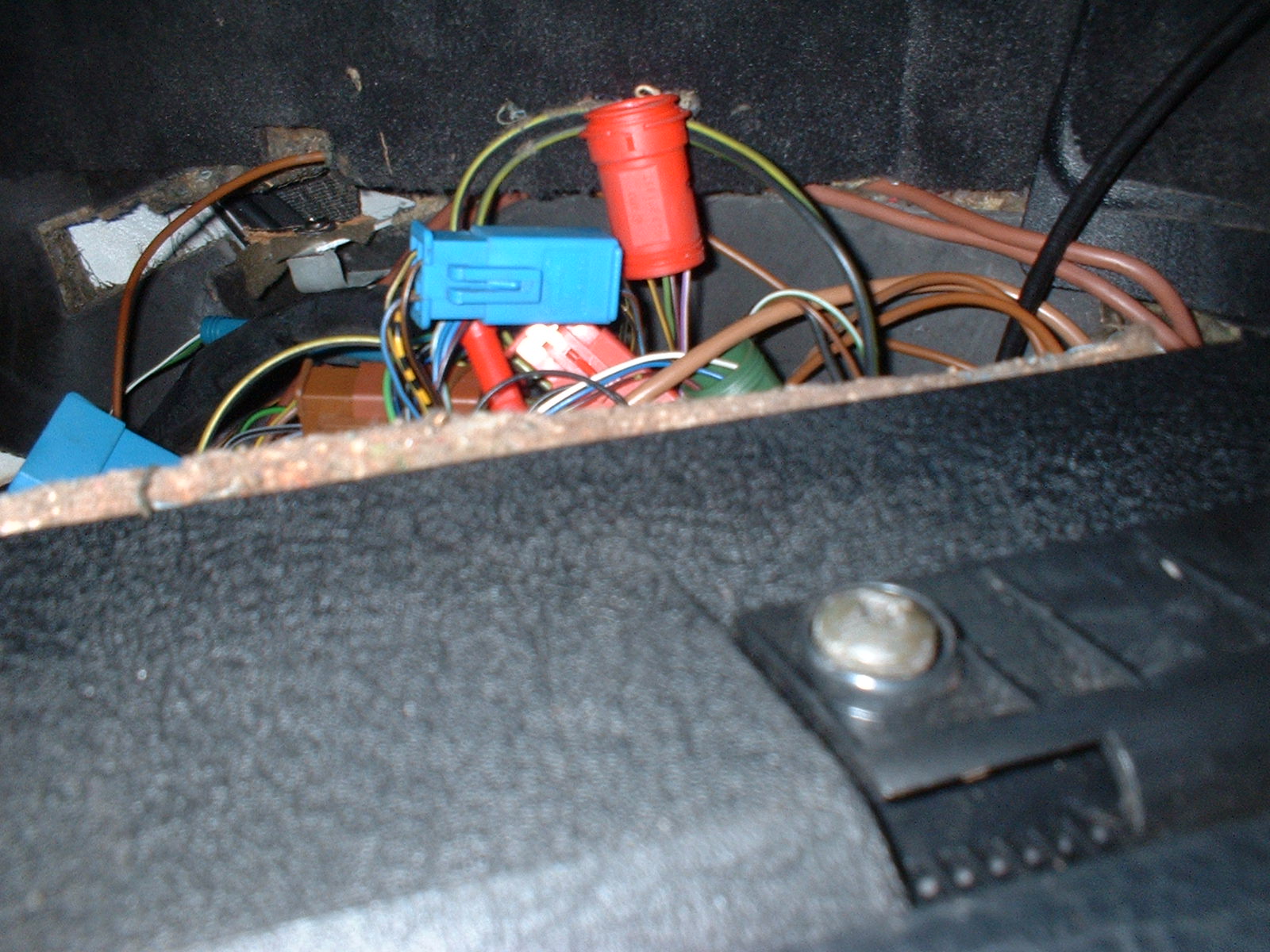
This is the connector underneath the fusebox that connects to the
airflow potentiometer. I think..... (still to be confirmed)
Light sensor fitted to left hand side of the binnacle. It was a much
tighter fit than the existing vent moulding
The Rear Window Demist switch has to be moved down one place to make
way for the computer switch.
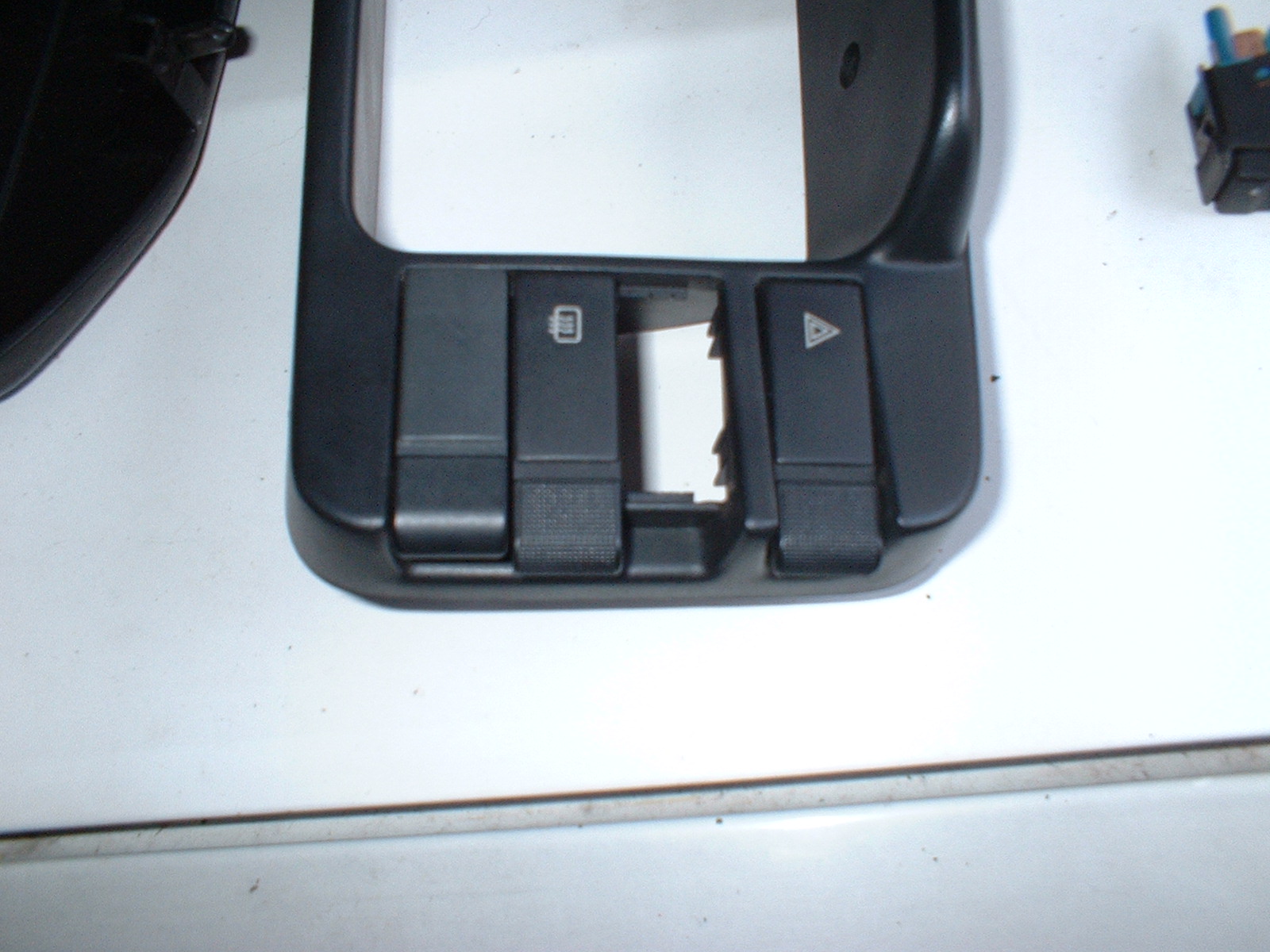
Computer switch, and the new and old dimmer switches. The new dimmer
switch has the white chevron printed on it
All switches clipped into place
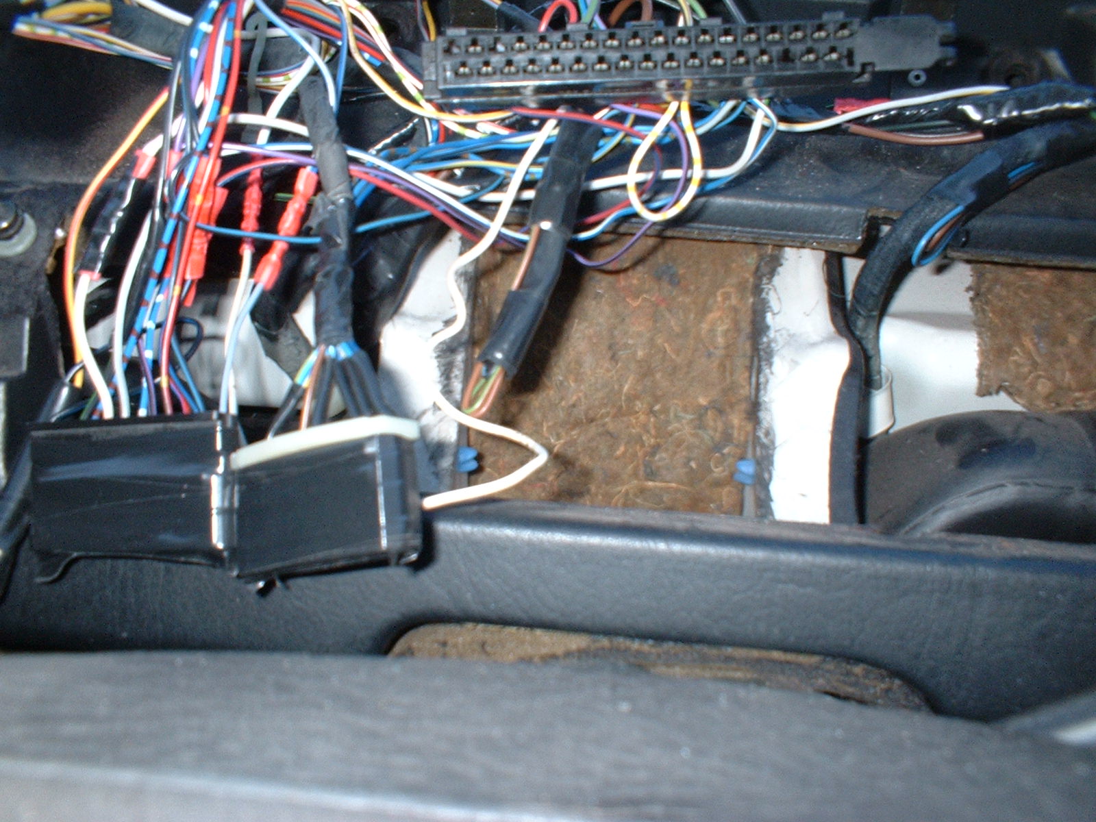
If you lift up part of the White connector, you can remove the pins
easily for soldering etc.
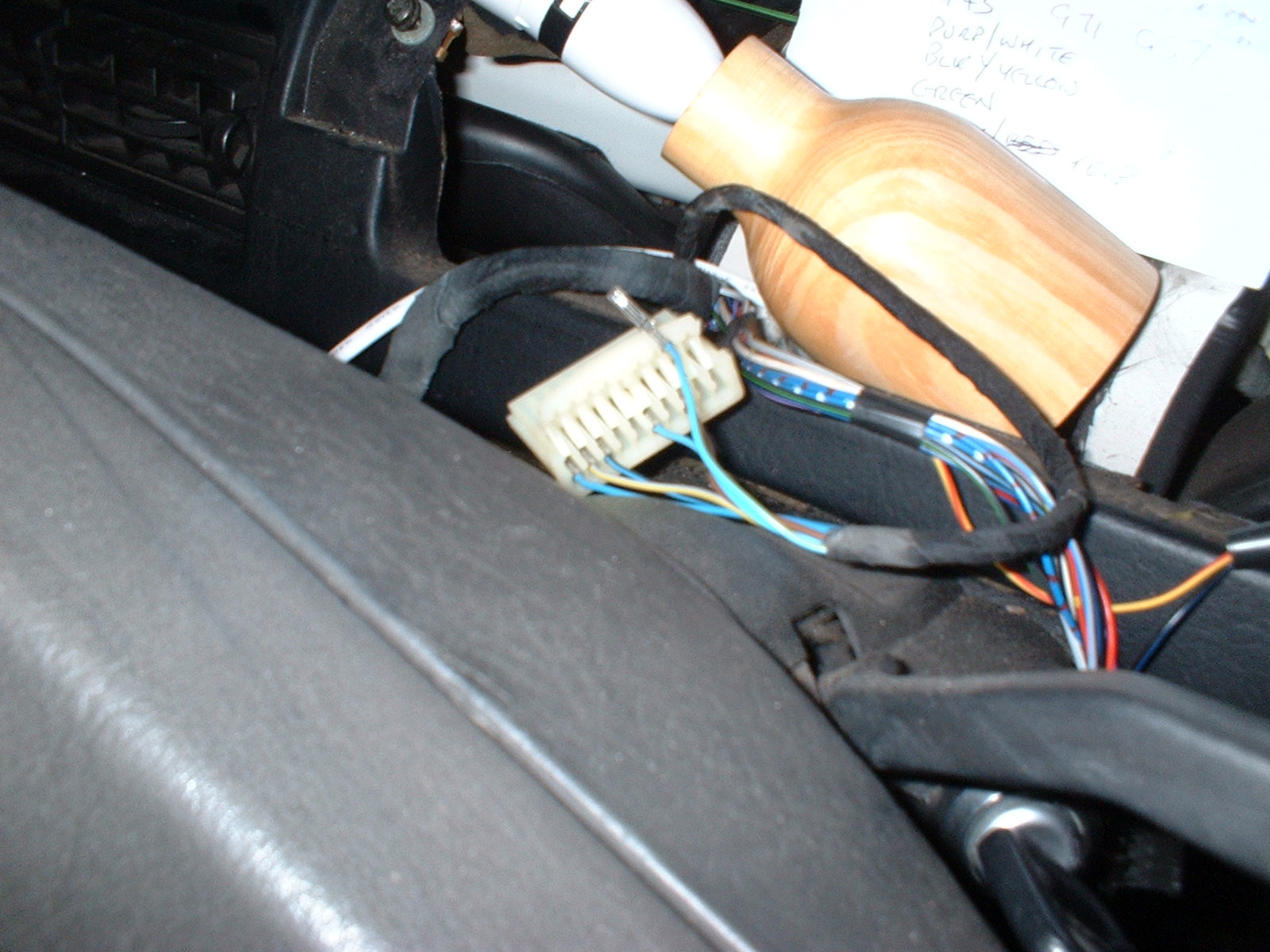
And extra wires can be piggybacked on.
And then re-assembled. I couldn't repeat this trick on the Black
connector, as I couldn't get the pins out......
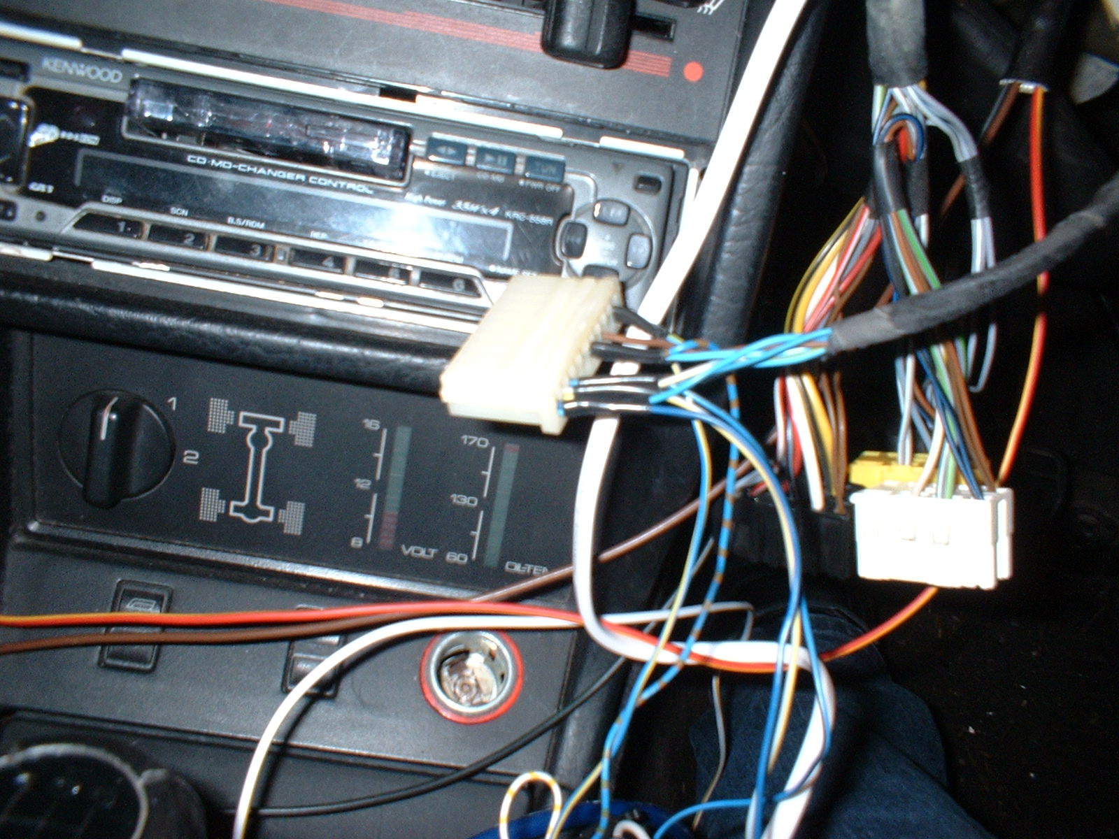
After much splicing, I have most of the wiring loom mods done. Note
the old connectors are still in situ, I should be able to remove the
digital unit and reconnect the old analog dash fairly easily if so
desired
I installed the switches without the fascia, until the dash is fully
debugged and is definitely working as desired. Makes any further
corrections / changes much easier.....
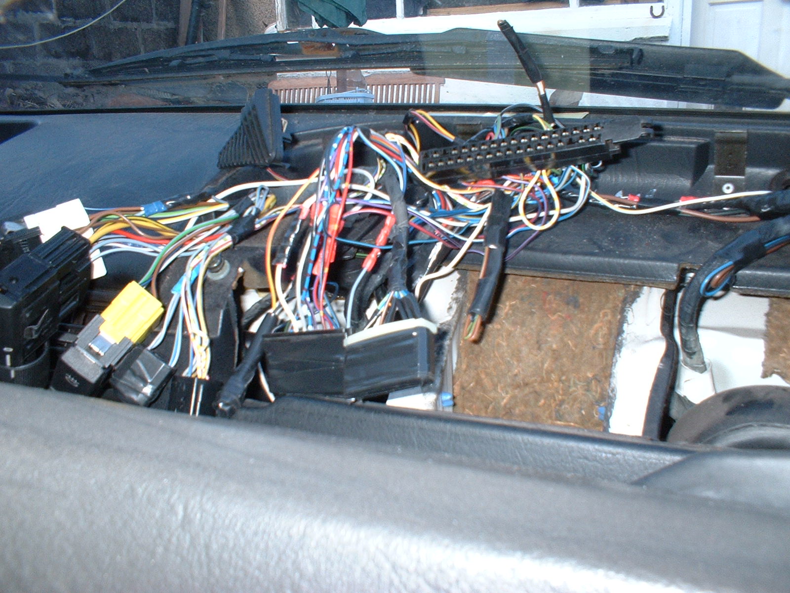
You can see the old connectors to the left of the new 35 pin item
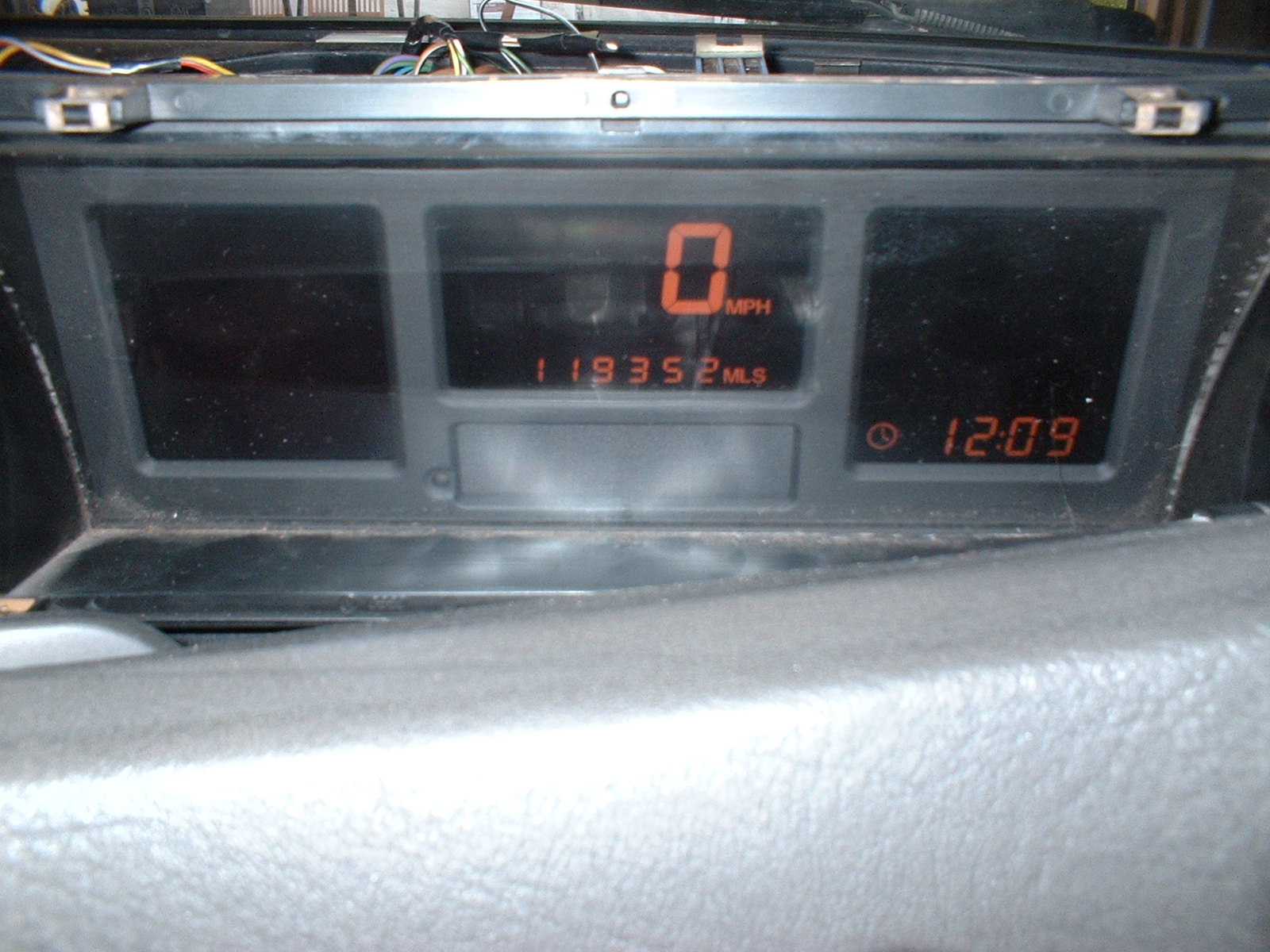
And here is the dash connected up. It's just loose at the moment
until the debugging is completed.

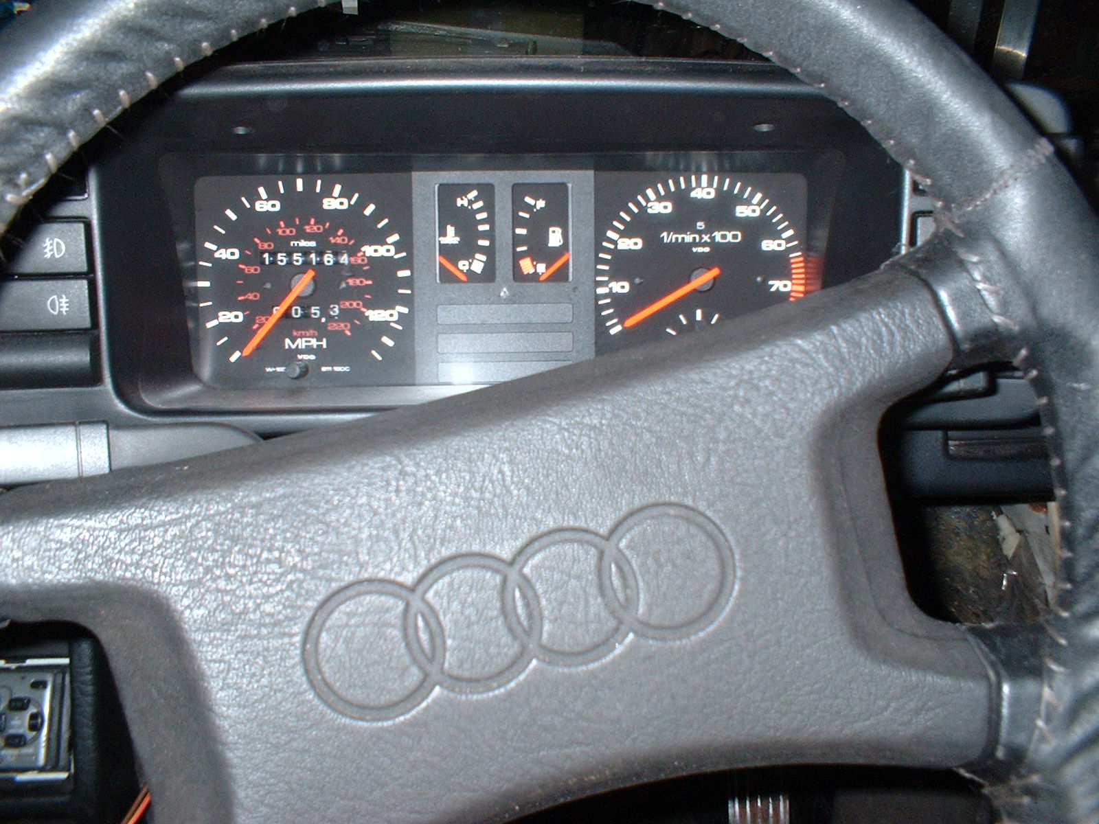
The moment of truth! It's alive, Egor............
This must be the dash self test, where all segments of the LCD
panels are switched on to show that they are all functional....
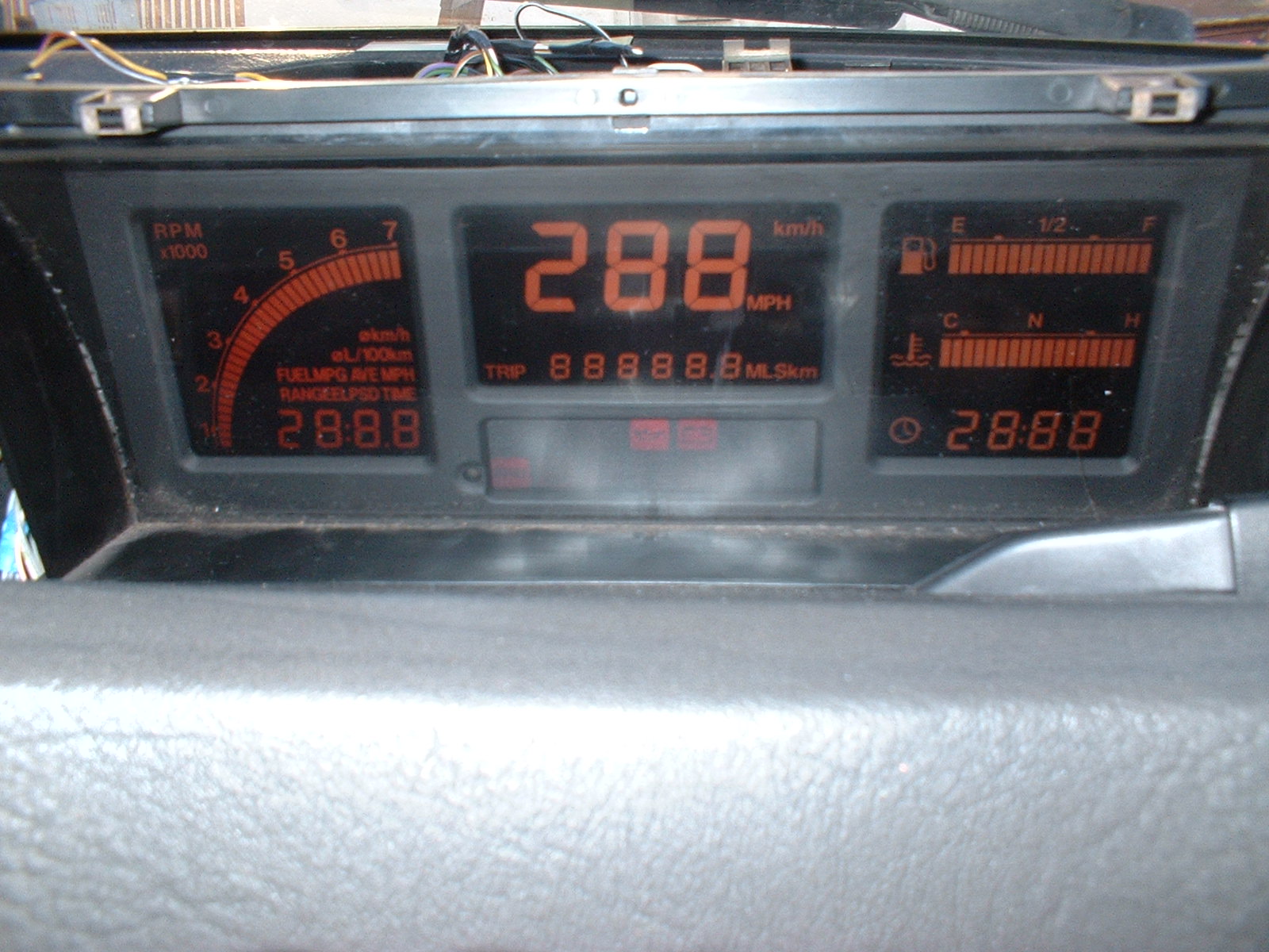
After a couple of seconds, it returns to a more conventional
appearance
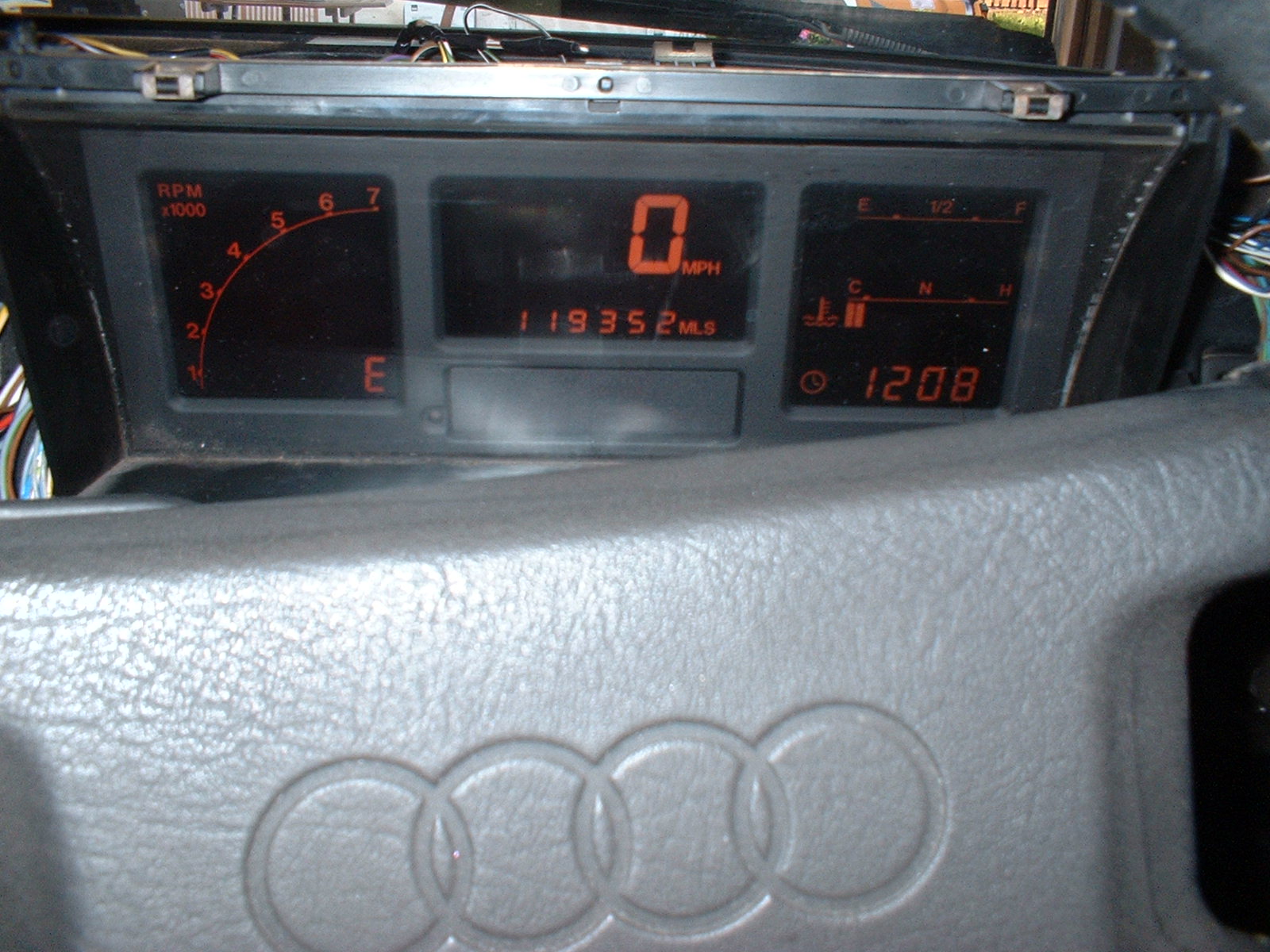
Dash display minimised by pushing on the dimmer switch button.
And this is the view from outside the car. Looks messy, but it's not
finished yet.....

The Warning lights on the old dash.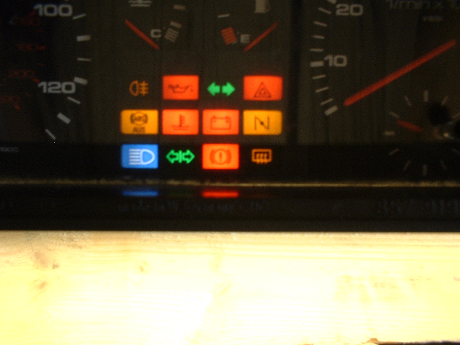
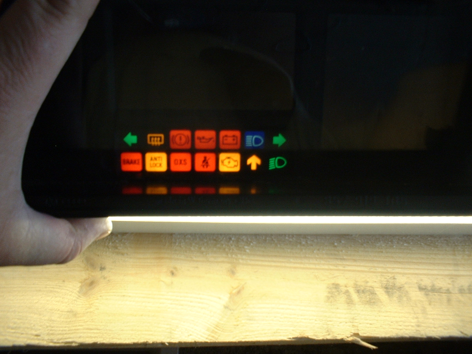
On the new
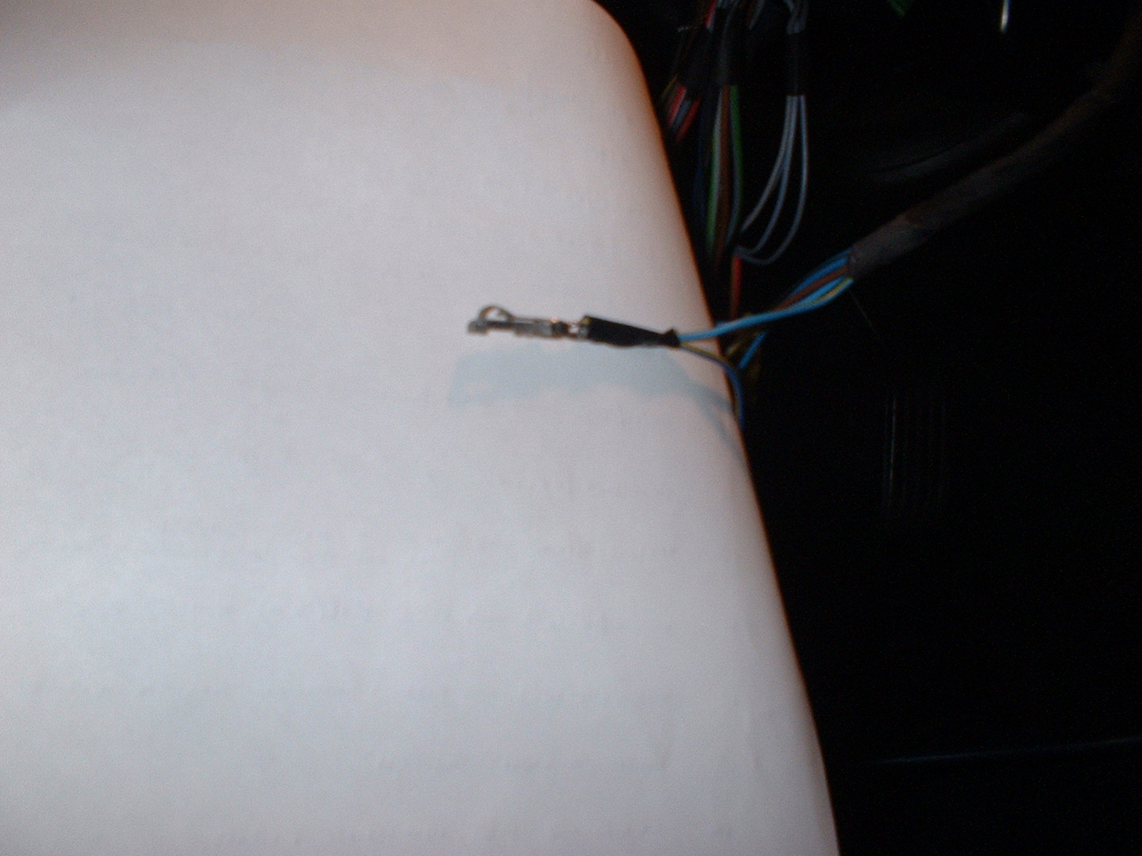
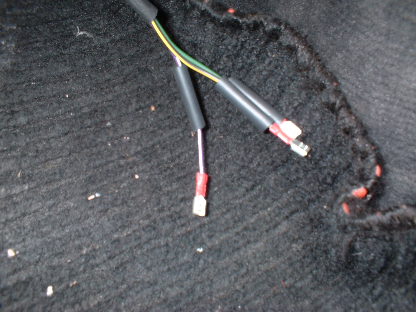
Wiring tails for the connections to the airflow potentiometer
underneath the fusebox

Now heatshrunk
Connected to existing 4 pin connector

Taped up to protect
End conected onto Tacho signal wire. Connects into the unused
connector location (pin 7) on the ignition unit under the dash
The digital dash is a different shape to the Analogue version in
this area, to make it fit you have to squash down the right fresh
air ducting
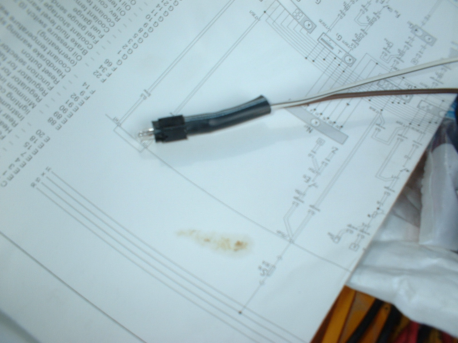
There is no connection on the DigiDash multiplug for the rear fog
light warning. So I used a spare ABS bulb holder, this connects to
pin 6 on the BC, and to ground.
More Work to be done
Although the dash is functional, and appears to be working ok, there are a few things that need to be done to complete the job.1. Put some fuel in, and check that the fuel guage reading changes (done)
2. At a later date, calibrate the fuel guage.
3. Connect up the airflow potentiometer, and verify that the dash is recieving information from it. (done)
4. Connect the Tacho drive signal (done)
5. Connect up the warning light for the rear fog lights. (done)
6. Repair the mouting lugs on the side of the dash unit (a particular Audi weakness)
7. Tidy up the wiring installation, and then refit everything to complete.
Connector Pin-outs that I used.
NOTE : My car is a 1985 KV engined Coupe
Quattro, Right Hand drive. These pinouts have worked for me, but may
not be right for your car. Use the information provided at your own
risk..........
And if you're no good at wiring, get someone who is to do it for
you........
White Connector (113 971 998A) at rear of KV quattro dash
| Pin number | Wire Colour | Connected to / Notes |
| 1 | Blue / Yellow | Coolant Low or overheated Connected to Pin 27 on the DigiDash |
| 2 | N/C (not connected) | |
| 3 | Brown | Ground |
| 4 | N/C | |
| 5 | Blue / Brown | Coolant Temp Guage Sender Connected to Pin 5 on the DigiDash |
| 6 | N/C | |
| 7 | N/C | |
| 8 | Black / Blue | Oil Pressure Warning Connected to Pin 17 on the DigiDash |
| 9 | Gray / Yellow | Handbrake Warning, Low Brake Fluid level warning Connected to Pin 16 on the DigiDash |
| 10 | Blue | Alternator Warning Light Connected to Pin 14 on the DigiDash |
Black Connector (443 972 957) at rear of KV quattro dash
| Pin number | Wire Colour | Connected to / Notes |
| 1 | Blue / Black | Connected to an empty bulb holder. ABS warning
light? Not used, no ABS on my car |
| 2 | N/C | |
| 3 | White / Black / Green | Indicator Warning Bulb Not used |
| 4 | Blue / Brown | Emergency Light System Light Not used |
| 5 | White | Rear Window demist warning light Connected to Pin 35 on the DigiDash |
| 6 | White / Gray | Rear Foglight Warning light There is no connection on the DigiDash multiplug for the rear fog light warning. So I used a spare ABS bulb holder, this connects between pin 6 and ground. |
| 7 | Blue / White | Main Beam Warning light Connected to Pin 31 on the DigiDash |
| 8 | Black / Violet | Fuel Guage Sender Connected to Pin 24 on the DigiDash |
| 9 | Red / Black / Yellow | Rev counter Connection location not established yet. |
| 10 | Blue / Red | Clock Power Connected to Pin 19/20 on the DigiDash |
| 11 | Black / Blue + Black / L. Blue |
Connected to corresponding colour conductor on rear window de-mister switch |
| 12 | Blue / Gray | Dimmer Connected to corresponding colour conductor on the Dimmer Switch. |
Digital Dash Wiring pinout
| Pin number | Wire Colour | Connected to / Notes |
| 1 | N/C (not connected) | |
| 2 | White / Red | Dimmer Switch Pin 2 |
| 3 | N/C | |
| 4 | Green / Violet | Electronic Ignition system Control Unit Connected to Pin 7 (not populated on my car) |
| 5 | Red / Yellow | Speed Sensor Pin 2 |
| 6 | Blue / Green | Computer Switch Pin 1 |
| 7 | Green / Blue | Computer Switch Pin 4 |
| 8 | Gray / Red | Dash Light Sensor Pin 2 |
| 9 | Green / Violet | Computer Switch Pin 5 |
| 10 | Yellow / Black | Pin 1 on Airflow Sensor (white / yellow) |
| 11 | White / Yellow | Fuse S16 (30A) on Busbar X Connected to circuit at the demister switch |
| 12 | White / Yellow | Dimmer Switch Pins 1 and 6 |
| 13 | White | Light Switch |
| 14 | Blue | Alternator Warning light Connected to Pin 10 on the White analog dash connector (WC) |
| 15 | 2 x Black / Blue | Rear Windows De-mister Switch |
| 16 | Gray / Yellow | Handbrake warning Light. Connected to Pin 5 WC |
| 17 | N/C | |
| 18 | Black / Green | Right hand indicator. Connected to corresponding colour conductor on the Hazard warning switch |
| 19 | Red / Blue | This Pins linked together. Fuse S4 (15A) Busbar 30. Connected to Pin 10 on the Black analog dash connector (BC) |
| 20 | ||
| 21 | Brown | These pins linked together.
Ground Connected to the chassis |
| 22 | ||
| 23 | Black / Red | Seat belt warning. Not used on my car |
| 24 | Violet / Black | Fuel Guage sender. Connected to Pin 8 BC |
| 25 | White / Green | Dimmer Switch Pin 4 |
| 26 | Blue / Brown | Coolant Temp Sender Connected to Pin 5 WC |
| 27 | Blue / Yellow | Low Coolant Connected to Pin 1 WC |
| 28 | White / Violet | Pin 3 on Airflow sensor |
| 29 | Green | Pin 2 on Airflow sensor |
| 30 | Yellow | Dash Light Sensor Pin 1 |
| 31 | Blue / White | Headlight Hi-Beam Connected to Pin 7 BC |
| 32 | Gray / Brown | Seat Belt Warning. Not used on my car |
| 33 | N/C | |
| 34 | Black / White | Left hand indicators Connected to corresponding colour conductor on the Hazard warning switch |
| 35 | White | Rear Window Demister. Connected to Pin 5 BC |
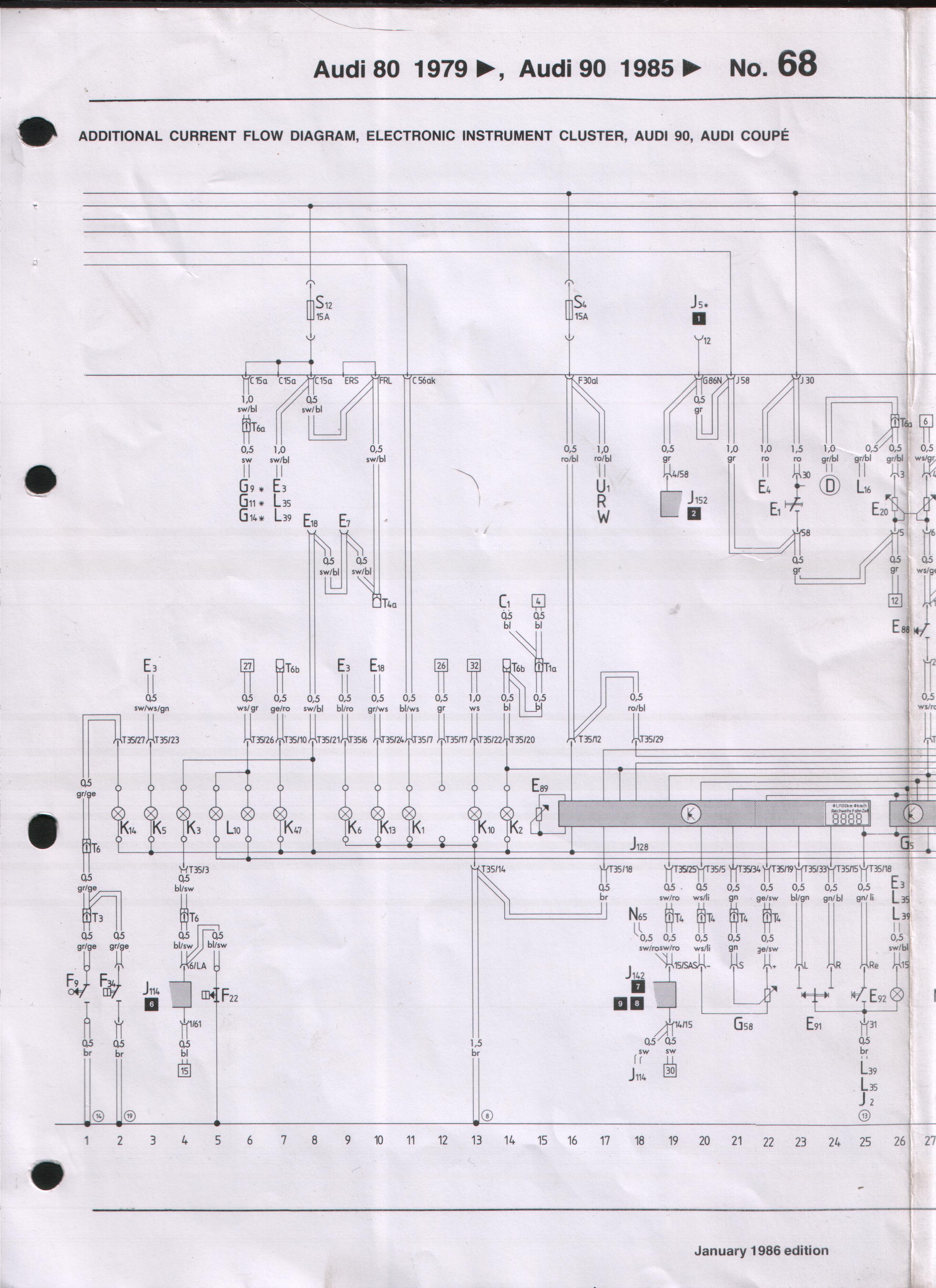
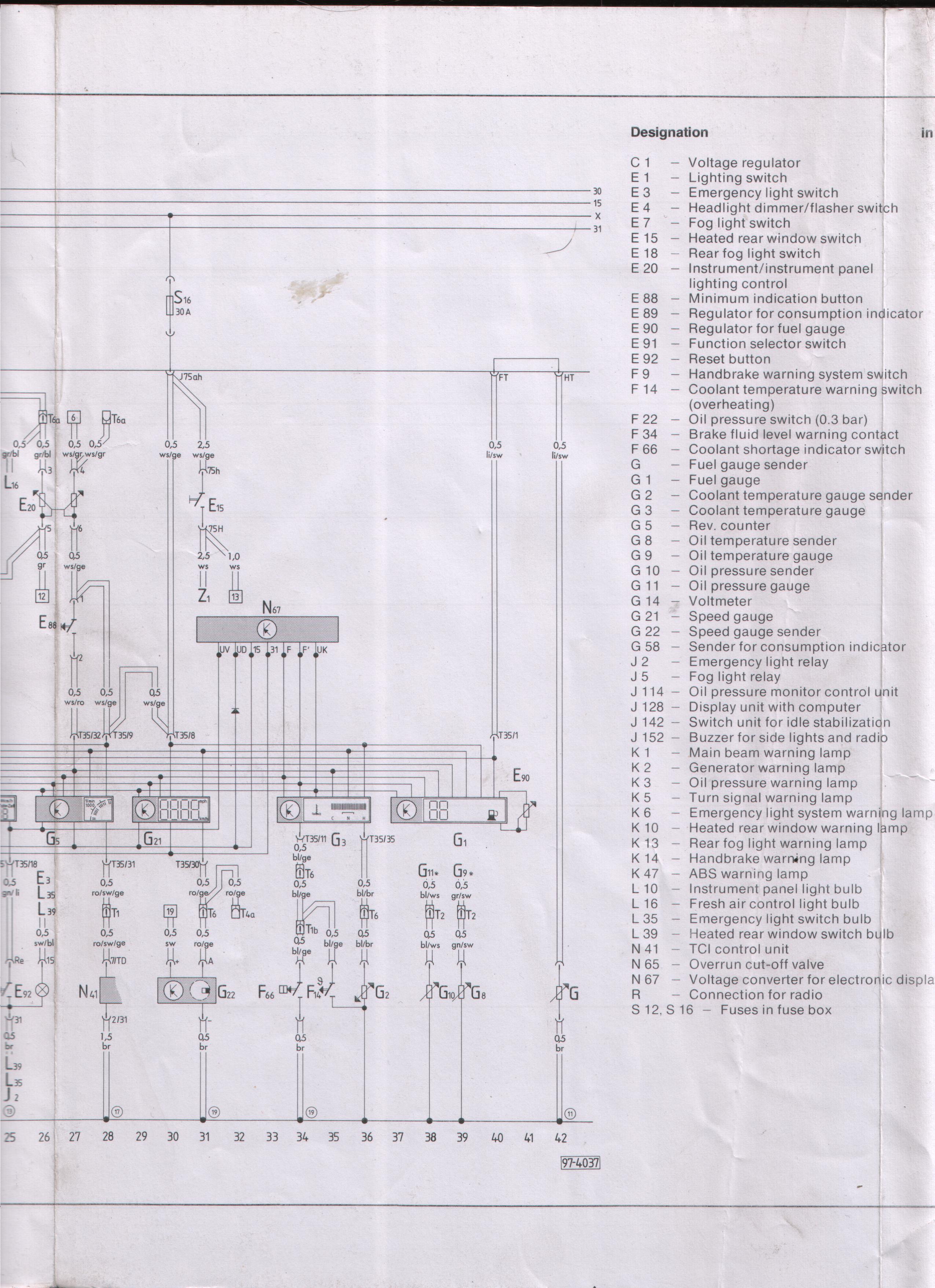
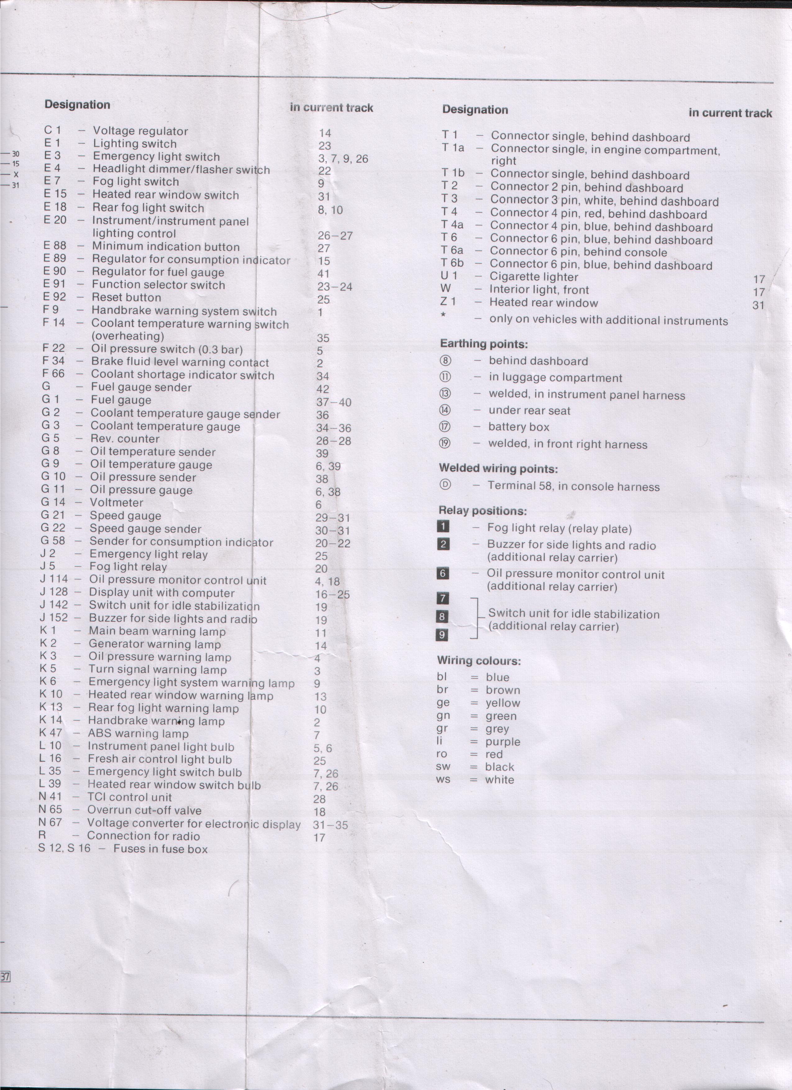
Wiring Diagram for the CQ with the green digital Dash installed
Corrections, Ommissions, Errata, etc.
I'm not perfect! Hey, but who is? So if you find any errors, omissions, or whatevers on this page, please contact me on this email address and let me know. Additionaly, if you have any more usefull information that could be added to this page, then please send it to me or contact me.........Thanks in advance!Click Here to email me